
Transistor and method of manufacturing the same

Active Publication Date: 2006-02-23
SAMSUNG ELECTRONICS CO LTD
View PDF15 Cites 75 Cited by
  • Summary
  • Abstract
  • Description
  • Claims
  • Application Information

AI Technical Summary

Benefits of technology

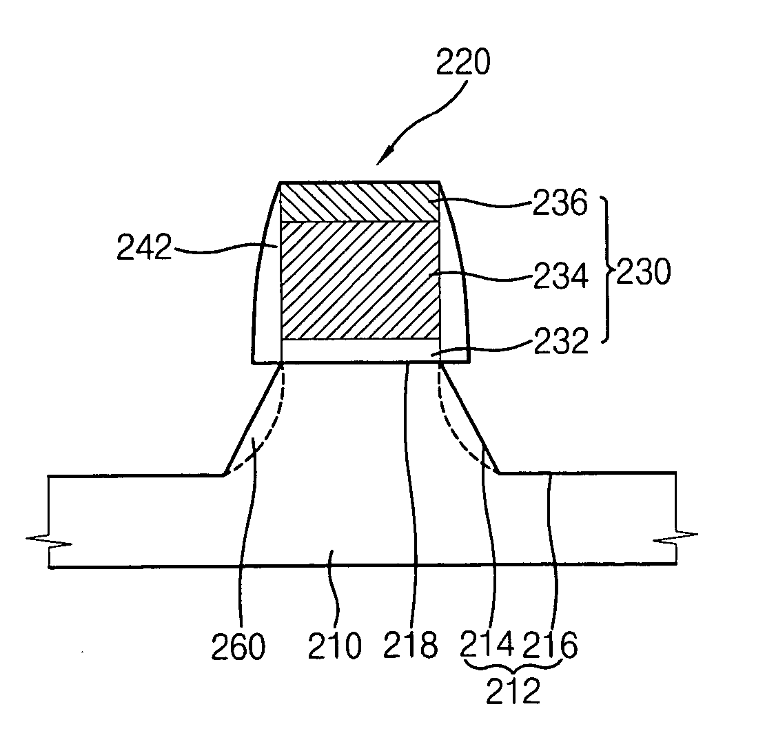
[0011] The present invention provides a highly integrated transistor including an improved structure that has excellent electrical characteristics.
[0015] According to another embodiment of the present invention, a halo implantation region is formed at a portion of the semiconductor substrate that makes contact with the third surface of the semiconductor substrate. The halo implantation region prevents impurities doped into the impurity regions from diffusing into the semiconductor substrate.
[0032] According to one embodiment of the present invention, before etching the semiconductor substrate to form the second surface and the third surface, halo dopants are implanted into the semiconductor substrate to form a preliminary halo implantation region. The preliminary halo implantation region is partially removed during the etching process to form a halo implantation region making contact with the side face, thereby preventing the impurities from diffusing into the semiconductor substrate.
[0036] In one embodiment, the method further comprises, prior to forming the second spacer, implanting halo dopants into the semiconductor substrate using the first spacer as an ion implantation mask to form a preliminary halo implantation region, and partially removing the preliminary halo implantation region while forming the recess to form a halo implantation region making contact with the side face, the halo implantation region preventing the impurities from diffusing into the semiconductor substrate.
[0050] According to the present invention, since the impurity regions have side faces of the {111} crystal plane, a PN junction may be steeply formed. Thus, generating a short channel effect between the impurity regions may be prevented so that a transistor having improved electrical characteristics is obtained.

Problems solved by technology

In the conventional transistor, an interface between the source / drain regions and the substrate may be damaged due to a hot carrier effect caused by rapid electrons.
When punch-through occurs in the transistor, the transistor may fail completely.
Therefore, the conventional method may not be easily employed for a highly integrated transistor having a gate width of below about 10 nm.

Method used


Image

  • Transistor and method of manufacturing the same
  • Transistor and method of manufacturing the same
  • Transistor and method of manufacturing the same

Examples


embodiment 1

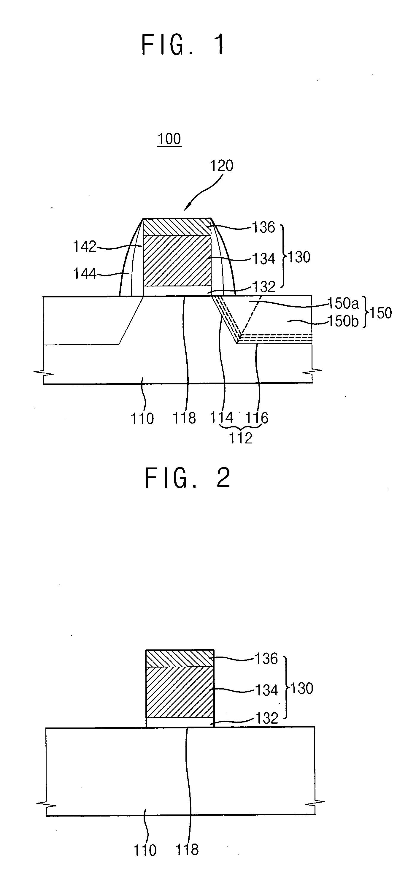
[0083]FIG. 1 is a cross sectional view illustrating a transistor in accordance with a first embodiment of the present invention.

[0084] Referring to FIG. 1, a transistor 100 of the present embodiment includes a semiconductor substrate 110 such as a silicon (Si) substrate or a silicon-germanium (Si—Ge) substrate, a gate structure 120 formed on the semiconductor substrate 110, two epitaxial layers 150 formed at portions of the semiconductor substrate 110 adjacent to the gate structure 120, and impurity regions respectively formed in the epitaxial layers 150.

[0085] The semiconductor substrate 110 has a first surface 118 including silicon oriented along a {100} crystal plane, a second surface 116 oriented along a {100} crystal plane, and a third surface 114 oriented along a {111} crystal plane. The gate structure 120 is formed on the first surface 118 of the substrate 110.

[0086] Two recesses 112 are respectively formed at portions of the first surface 118 adjacent to the gate structur...

embodiment 2

[0106] A transistor of a second embodiment of the present invention has elements substantially identical to those of the transistor in FIG. 1 except impurity regions 170 having side faces substantially different from those of epitaxial layers 150 as shown in FIG. 7. The side faces of the impurity regions 170 are respectively positioned between a central portion of a gate pattern 130 and side faces of the epitaxial layers 150. Thus, any further detailed description concerning the transistor of the present embodiment will not be repeated.

[0107]FIGS. 6 and 7 are cross sectional views illustrating a method for manufacturing the transistor in accordance with the present embodiment. In the present embodiment, processes for manufacturing the transistor are substantially identical to those described with reference to FIGS. 2 to 5 except for a process for forming the impurity regions 170.

[0108] Referring to FIG. 6, impurities including carbon, boron, phosphorous, etc, are implanted into th...

embodiment 3

[0111] A transistor of a third embodiment of the present invention has a structure substantially identical to that of the transistor in FIG. 1. Thus, a method of manufacturing the transistor of the present embodiment will be described with reference to FIGS. 8 to 12.

[0112] FIGS. 8 to 12 are cross sectional views illustrating the method of manufacturing the transistor according to the third embodiment of the present invention. In the present embodiment, after first spacers 142 are formed on sidewalls of a gate pattern 130, epitaxial layers 150 are formed in recesses 112 before second spacers 144 are formed on the first spacers 142.

[0113] Referring to FIG. 8, the gate pattern 130 including an insulation layer pattern 132, a conductive layer pattern 134 and a hard mask layer pattern 136 are formed on a surface 118 of a semiconductor substrate 110. The surface 118 includes silicon oriented along the {100} crystal plane.

[0114] Referring to FIG. 9, the first spacers 142 including a nit...


PUM


Abstract

A transistor includes a semiconductor substrate that has a first surface of a {100} crystal plane, a second surface of the {100} crystal plane having a height lower than that of the first surface, and a third surface of a {111} crystal plane connecting the first surface to the second surface. First heavily doped impurity regions are formed under the second surface. A gate structure is formed on the first surface. An epitaxial layer is formed on the second surface and the third surface. Second heavily doped impurity regions are formed at both sides of the gate structure. The second heavily doped impurity regions have side faces of the {111} crystal plane so that a short channel effect generated between the impurity regions may be prevented.

Description

CROSS REFERENCE TO RELATED APPLICATION [0001] This application is a Continuation-In-Part of U.S. patent application Ser. No. 11 / 071,018, entitled “TRANSISTOR AND METHOD OF MANUFACTURING THE SAME”, filed on Mar. 3, 2005. This application also claims priority under 35 USC § 119 to Korean Patent Application Nos. 2004-65736, filed on Aug. 20, 2004, and 2005-63072, filed on Jul. 13, 2005. The contents of all of these documents are herein incorporated by reference in their entirety for all purposes.BACKGROUND OF THE INVENTION [0002] 1. Field of the Invention [0003] The present invention relates to a transistor and a method of manufacturing the transistor. More particularly, the present invention relates to a highly integrated transistor that includes improved impurity regions, and a method of manufacturing the transistor. [0004] 2. Description of the Related Arts [0005] In general, a transistor of a semiconductor device includes a gate structure formed on a semiconductor substrate, and so...

Claims


Application Information

Patent Timeline
IPC IPC(8): H01L27/12H01L29/06
CPCH01L29/045H01L29/6656H01L29/7834H01L29/66636H01L29/7833H01L29/6659
Inventor UENO, TETSUJIRHEE, HWA-SUNGLEE, HOSHIN, DONG-SUKLEE, SEUNG-HWAN
Owner SAMSUNG ELECTRONICS CO LTD
Learn More