
Encapsulation of high temperature thermoelectric modules

Active Publication Date: 2016-03-03
GM GLOBAL TECH OPERATIONS LLC
View PDF3 Cites 5 Cited by
  • Summary
  • Abstract
  • Description
  • Claims
  • Application Information

AI Technical Summary

Benefits of technology

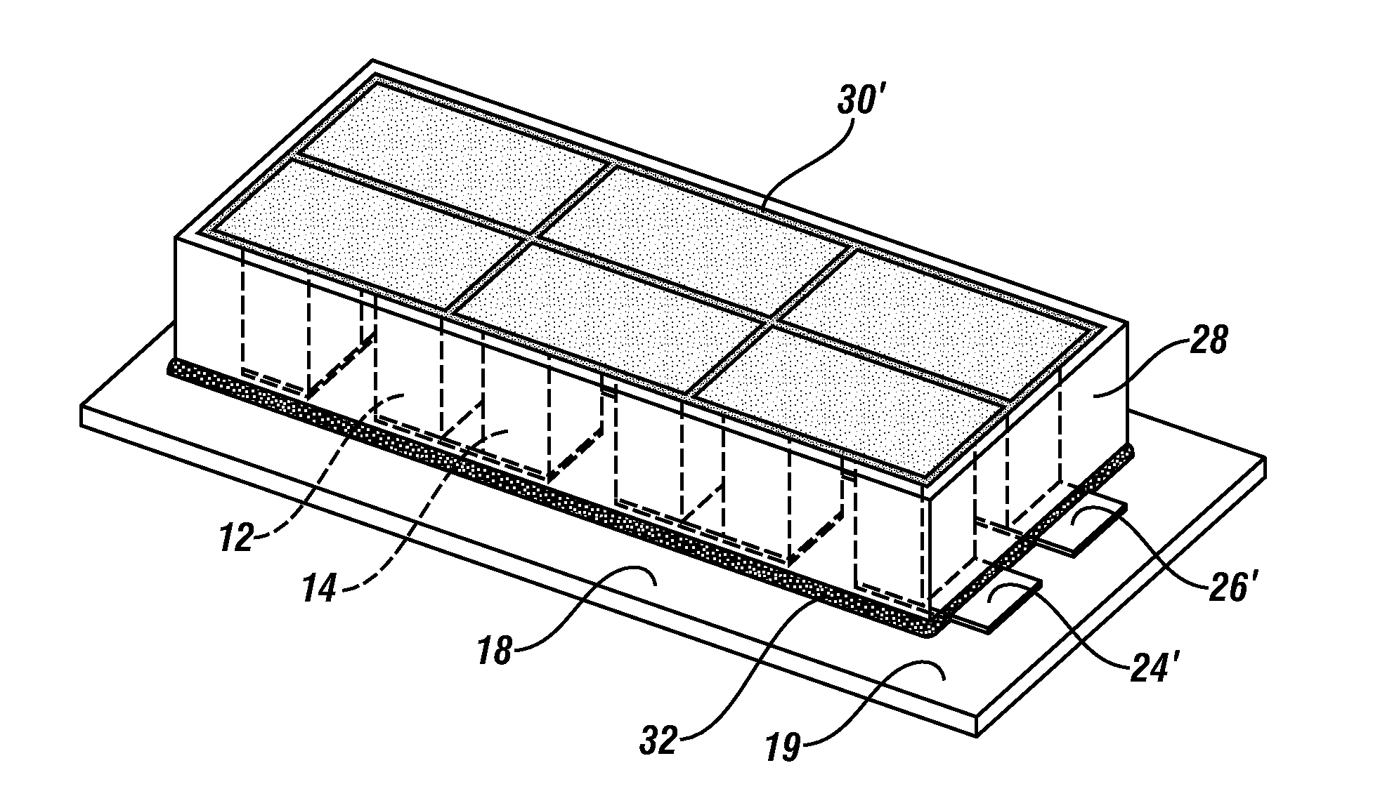
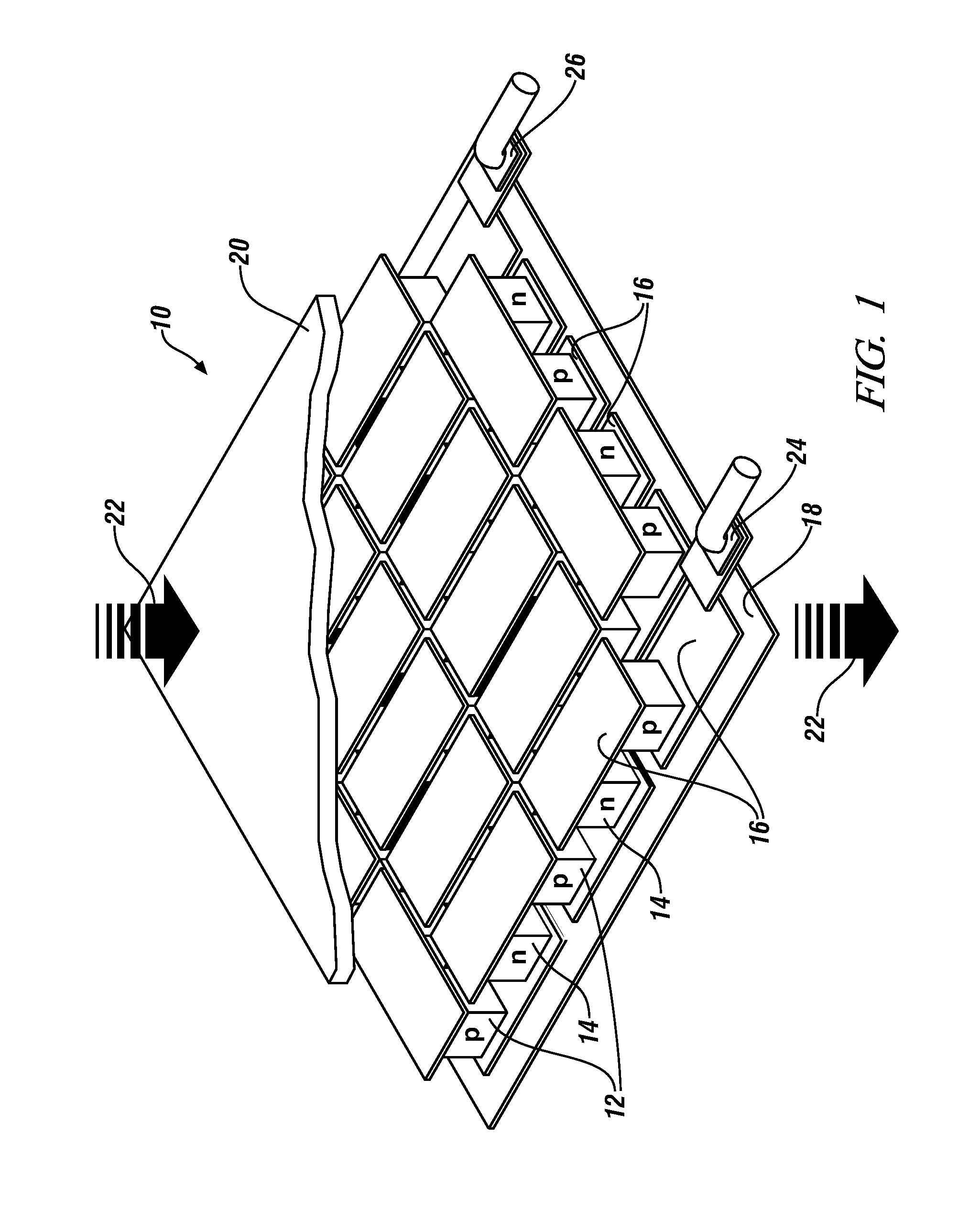
This patent is about a way to protect the thermoelectric elements in a device from oxidation, which can cause damage to the device. The invention aims to prevent the entry of oxidizing gases like oxygen or water vapor into the device. The solution involves using a thin, low thermal conductivity foil shield to enclose the thermoelectric elements and their substrates. This shield helps to maintain the proper geometry and prevents the elements from overheating. The foil shield can be attached to the substrates using enamel powder or an enamel precursor, which forms a strong joint that is resistant to oxidation. Overall, this invention helps to protect the thermoelectric device from damage and ensures its performance is not compromised.

Problems solved by technology

Under these operating conditions the thermoelectric composition may degrade.

Method used


Image

  • Encapsulation of high temperature thermoelectric modules
  • Encapsulation of high temperature thermoelectric modules
  • Encapsulation of high temperature thermoelectric modules

Examples


first embodiment

[0076]In the first embodiment, the thermoelectric device may be fully assembled and brazed prior to sealing by enameling. Since the enameling temperature for the exemplary Thomson Enamel ‘6000 clear’ enamel is about 650° C. the braze alloy should preferably have a solidus temperature greater than 650° C., although if the melting range is large say 100° C. or more, some minor melting might be acceptable enabling a solidus temperature of 640° C.-650° C. or so provided the liquidus temperature is not so high as to degrade the thermoelectric elements during brazing, even when conducted under inert atmosphere. Some suitable compositions with solidus / liquidus temperatures in parentheses may include: Cu86.8Sn7P6.2 (657 / 688° C.); Cu92.8P7.2 (710 / 793° C.); and Ag40Cu30Zn30 (674 / 727° C.).

second embodiment

[0077]In the second embodiment the thermoelectric device will be brazed after the vitreous enamel is applied, so that the liquidus temperature of the braze alloy should not exceed the temperature at which the enamel will undergo extensive flow. For the exemplary Thomson Enamel ‘6000 clear’ enamel, which undergoes extensive flow at about 700° C., suitable braze alloys may include: Al94.75 Si5.25 (575 / 630° C.); Al92.5 Si7.5 (575 / 615° C.); and Al90Si10 (575 / 590° C.), all of which are suitable for aluminum interconnects. Where sustained temperatures of about 600° C. or so will be encountered in service, a higher melting point brazing alloy such as eutectic alloy Cu75.9Ag17.6P6.5 (643 / 643° C.) which is suitable for copper interconnects may be preferred. Of course, the use of higher flow temperature enamels will enable the use of higher melting temperature braze alloys.

[0078]The particular thermoelectric elements, vitreous enamel composition, brazing alloy compositions, and temperatures c...


PUM


Abstract

A method of encapsulating a thermoelectric device and its associated thermoelectric elements in an inert atmosphere and a thermoelectric device fabricated by such method are described. These thermoelectric devices may be intended for use under conditions which would otherwise promote oxidation of the thermoelectric elements. The capsule is formed by securing a suitably-sized thin-walled strip of oxidation-resistant metal to the ceramic substrates which support the thermoelectric elements. The thin-walled metal strip is positioned to enclose the edges of the thermoelectric device and is secured to the substrates using gap-filling materials. The strip, substrates and gap-filling materials cooperatively encapsulate the thermoelectric elements and exclude oxygen and water vapor from atmospheric air so that the elements may be maintained in an inert, non-oxidizing environment.

Description

[0001]This invention was made with U.S. Government support under Agreement No. DE-EE0005432 awarded by the Department of Energy. The U.S. Government may have certain rights in this invention.TECHNICAL FIELD[0002]This invention pertains to methods of encapsulating thermoelectric devices intended for use at temperatures of 400° C. to 600° C. in oxygen-containing atmospheres to protect against in-service, high temperature oxidation of the thermoelectric elements in the devices.BACKGROUND OF THE INVENTION[0003]Continuing pressure for improving the fuel consumption of automobiles and light trucks has raised interest in extracting energy from the heat contained in the exhaust gas that is normally lost when the exhaust gas is vented to the atmosphere. One approach under consideration is to use thermoelectric elements which generate an electrical potential difference when a temperature gradient is established and maintained so that one end of the thermoelectric element is maintained at a hi...

Claims


Application Information

Patent Timeline
IPC IPC(8): H01L35/32H01L35/34
CPCH01L35/34H01L35/325H10N10/01H10N10/17H10N19/101
Inventor SALVADOR, JAMES, R.SAKAMOTO, JEFFREYPARK, YOUNGSAM
Owner GM GLOBAL TECH OPERATIONS LLC
Learn More