
Air-conditioning apparatus including unit for increasing heating capacity

a technology of air-conditioning apparatus and heating capacity, which is applied in the direction of domestic cooling apparatus, heating types, defrosting, etc., can solve the problems of affecting normal operation, reducing the actual exertion of capacity over the inherent capacity, and affecting normal operation, so as to reduce increase the amount of refrigerant circulation, and suppress the rise of the discharge temperature of compressor

Active Publication Date: 2014-02-06
MITSUBISHI ELECTRIC CORP
View PDF1 Cites 23 Cited by
  • Summary
  • Abstract
  • Description
  • Claims
  • Application Information

AI Technical Summary

Benefits of technology

The air-conditioning apparatus described in this patent ensures that heat is added to the refrigerant by an external heat source, which reduces the evaporating temperature of the refrigerant in the refrigeration cycle. As a result, the compressor's discharge temperature is suppressed, allowing for continued heating operation in low outdoor air temperature environments. Additionally, the increased evaporating temperature of the refrigerant increases the amount of refrigerant circulation and heating capacity.

Problems solved by technology

However, even in an injection type air-conditioning apparatus, further drop in the outdoor air temperature will cause the heating capacity ratio (the actual exerted capacity over the inherent capacity) to drop.
Additionally, if the low outdoor air temperature drops even further, the evaporating temperature of the refrigeration cycle becomes low and the discharge temperature of the compressor increases, hindering normal operation due to the need to protect the compressor.

Method used


Image

  • Air-conditioning apparatus including unit for increasing heating capacity
  • Air-conditioning apparatus including unit for increasing heating capacity
  • Air-conditioning apparatus including unit for increasing heating capacity

Examples


embodiment 1

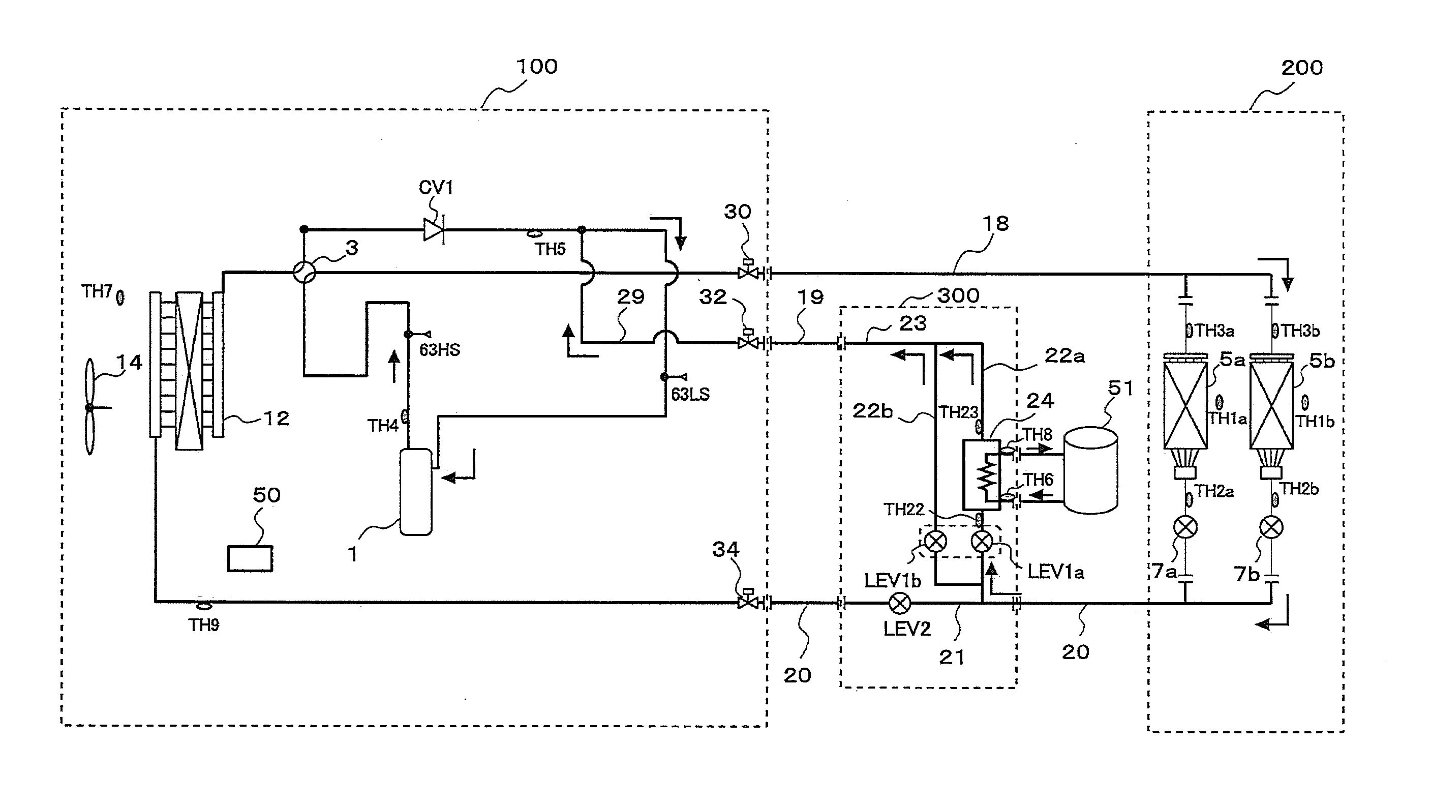
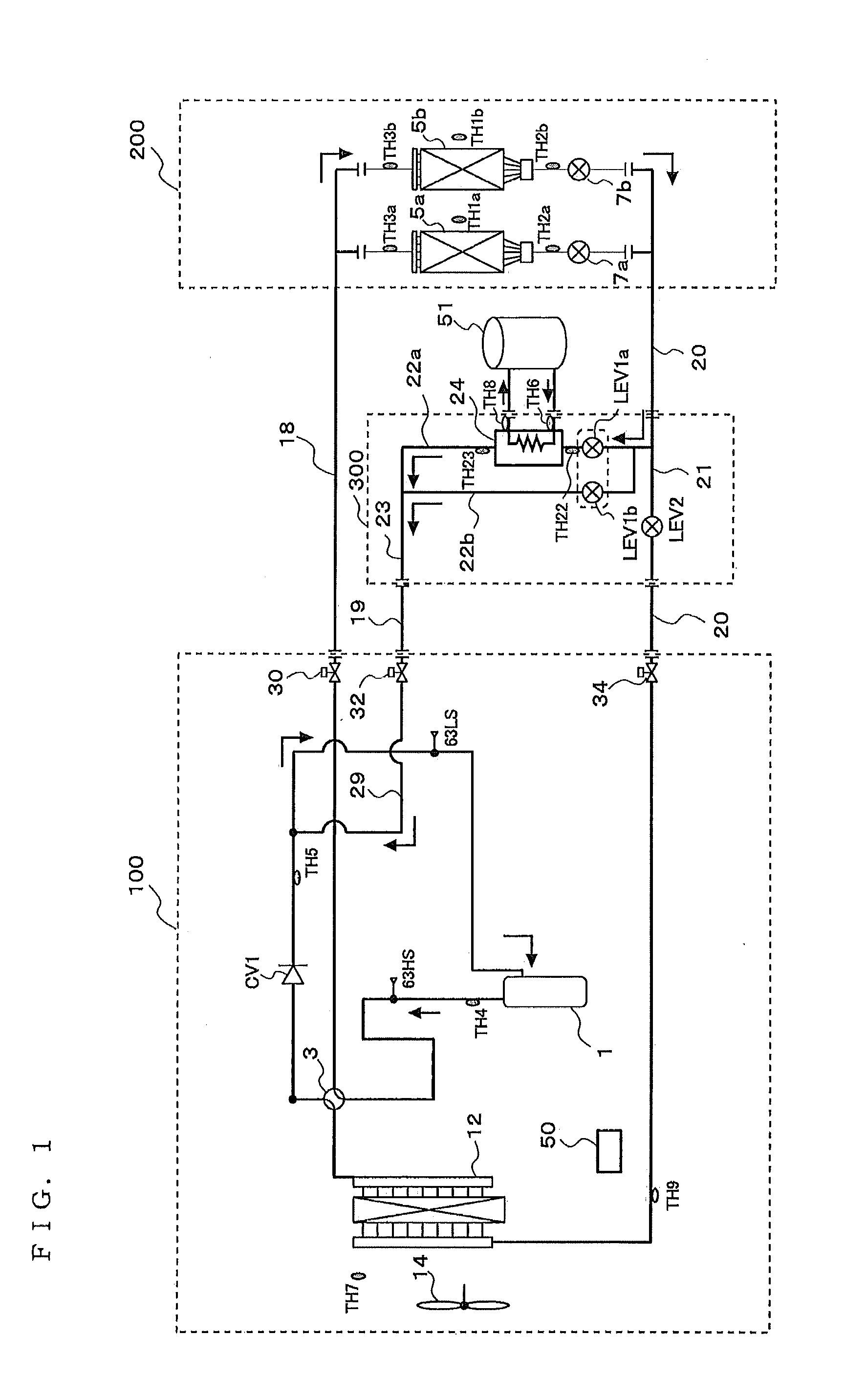
[0057]An air-conditioning apparatus of Embodiment 1 of the invention will be subsequently described with reference to FIG. 1. FIG. 1 is an air-conditioning apparatus capable of switching between a heating operation and a cooling operation. As illustrated in FIG. 1, a refrigerant circuit of a refrigeration cycle is formed by a compressor 1, a four-way valve 3 serving as a flow switching device, indoor heat exchangers 5a and 5b, indoor expansion valves 7a and 7b, a liquid piping expansion valve LEV2, and an outdoor heat exchanger 12. Note that the arrows in FIG. 1 indicate a refrigerant flow in a heating operation in which the outdoor heat exchanger 12 is not used.

[0058]The compressor 1, the four-way valve 3, and the outdoor heat exchanger 12 are disposed in an outdoor unit 100. The outdoor unit 100 is provided with a temperature sensor TH4 that detects a temperature of the refrigerant discharged from the compressor 1, a high-pressure sensor 63HS that detects a pressure of the refrige...

embodiment 2

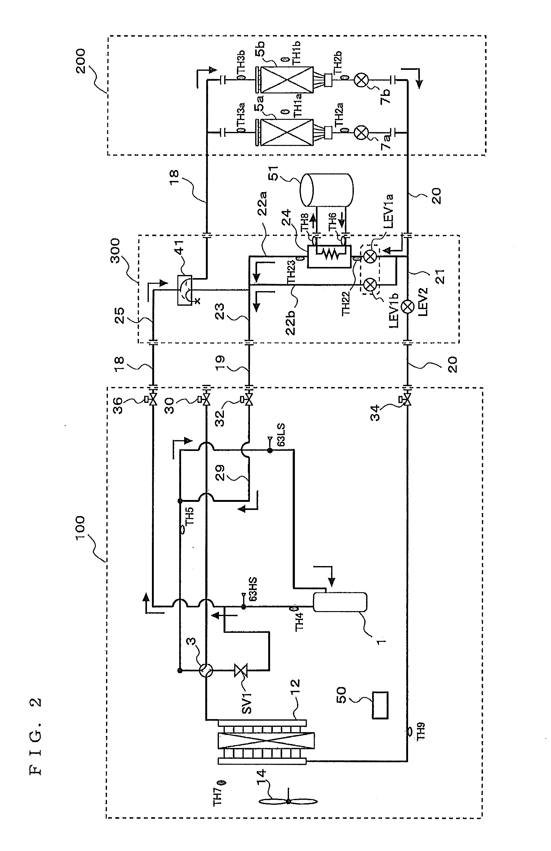
[0075]Next, an air-conditioning apparatus of Embodiment 2 of the invention will be described with reference to FIG. 2. FIG. 2 is an air-conditioning apparatus capable of switching between a heating operation and a cooling operation. As illustrated in FIG. 2, a refrigerant circuit of a refrigeration cycle is formed by a compressor 1, a four-way valve 41 serving as a flow switching device of indoor units to cooling / heating, indoor heat exchangers 5a and 5b, indoor expansion valves 7a and 7b, a liquid piping expansion valve LEV2, an outdoor heat exchanger 12, and a four-way valve 3. Note that the arrows in FIG. 2 indicate a refrigerant flow in a heating operation in which the outdoor heat exchanger 12 is not used.

[0076]The compressor 1, the four-way valve 3, and the outdoor heat exchanger 12 are disposed in an outdoor unit 100. The outdoor unit 100 is provided with a temperature sensor TH4 that detects a temperature of the refrigerant discharged from the compressor 1, a high-pressure s...

embodiment 3

[0092]Next, an air-conditioning apparatus of Embodiment 3 of the invention will be described with reference to FIG. 3. FIG. 3 is an air-conditioning apparatus capable of switching between a heating operation and a cooling operation. As illustrated in FIG. 3, a refrigerant circuit of a refrigeration cycle is formed by a compressor 1, a four-way valve 41 serving as a flow switching device of indoor units 200 to cooling / heating, indoor heat exchangers 5a and 5b, indoor expansion valves7a and 7b, a receiver 15, an outdoor expansion valve LEV2′, an outdoor heat exchanger 12, and a four-way valve 3. Note that the arrows in FIG. 3 indicate a refrigerant flow in a heating operation in which the outdoor heat exchanger 12 is not used.

[0093]The compressor 1, the four-way valve 3, the outdoor heat exchanger 12, the outdoor expansion valve LEV2′, and the receiver 15 are disposed in an outdoor unit 100. The outdoor unit 100 is provided with a temperature sensor TH4 that detects a temperature of t...


PUM


Abstract

An air-conditioning apparatus including a check valve in a passage between a first flow switching device and a suction side of a compressor, an expansion valve midway of a liquid extension piping, and an additional unit having a first bypass and a second bypass that are branched off from a passage between an indoor unit and the liquid expansion valve, and are connected to a passage between the check valve and the suction side of the compressor. The first bypass has, midway thereof, a first bypass expansion valve capable of controlling a throughput of refrigerant and an auxiliary heat exchanger that has a heat source different from the refrigerant, the auxiliary heat exchanger functioning as an evaporator heating the refrigerant flowing in the first bypass. The second bypass has, midway thereof, a second bypass expansion valve capable of controlling a throughput of refrigerant.

Description

TECHNICAL FIELD[0001]The present invention relates to an air-conditioning apparatus, and more particularly, to an air-conditioning apparatus including a unit for increasing heating capacity suitable for use in cold districts.BACKGROUND ART[0002]There is a known air-conditioning apparatus for carrying out heating under a low outdoor air temperature environment of about −10 degrees C. that performs injection of a gas refrigerant or a two-phase refrigerant into a compressor. However, even in an injection type air-conditioning apparatus, further drop in the outdoor air temperature will cause the heating capacity ratio (the actual exerted capacity over the inherent capacity) to drop.[0003]Additionally, if the low outdoor air temperature drops even further, the evaporating temperature of the refrigeration cycle becomes low and the discharge temperature of the compressor increases, hindering normal operation due to the need to protect the compressor.[0004]Meanwhile, there is a known air-co...

Claims


Application Information

Patent Timeline
Patent Type & Authority Applications(United States)
IPC IPC(8): F25B29/00F25D21/06F25B13/00
CPCF25B13/00F25B25/00F24F1/0003F24F13/30F25B41/00F25B43/00F25B41/20F25B41/24F25B25/005F25B2313/009F25B2313/0215F25B2313/0233F25B2313/02731F25B2313/02741F25B2400/16F25B2500/31F25B2600/2507F25B2700/2106
Inventor TANAKA, KOSUKEKASAI, TOMOHIKO
Owner MITSUBISHI ELECTRIC CORP
Learn More