
Small organic molecule based flow battery

a flow battery, organic technology, applied in the direction of indirect fuel cells, cell components, electrochemical generators, etc., can solve the problems of compromising the effectiveness of electrodes, limiting the use in a manned environment, such as the home, and limiting the price at large scale. , to achieve the effect of high current density, high efficiency and large-scale energy storag

Active Publication Date: 2016-02-11
PRESIDENT & FELLOWS OF HARVARD COLLEGE
View PDF10 Cites 17 Cited by
  • Summary
  • Abstract
  • Description
  • Claims
  • Application Information

AI Technical Summary

Benefits of technology

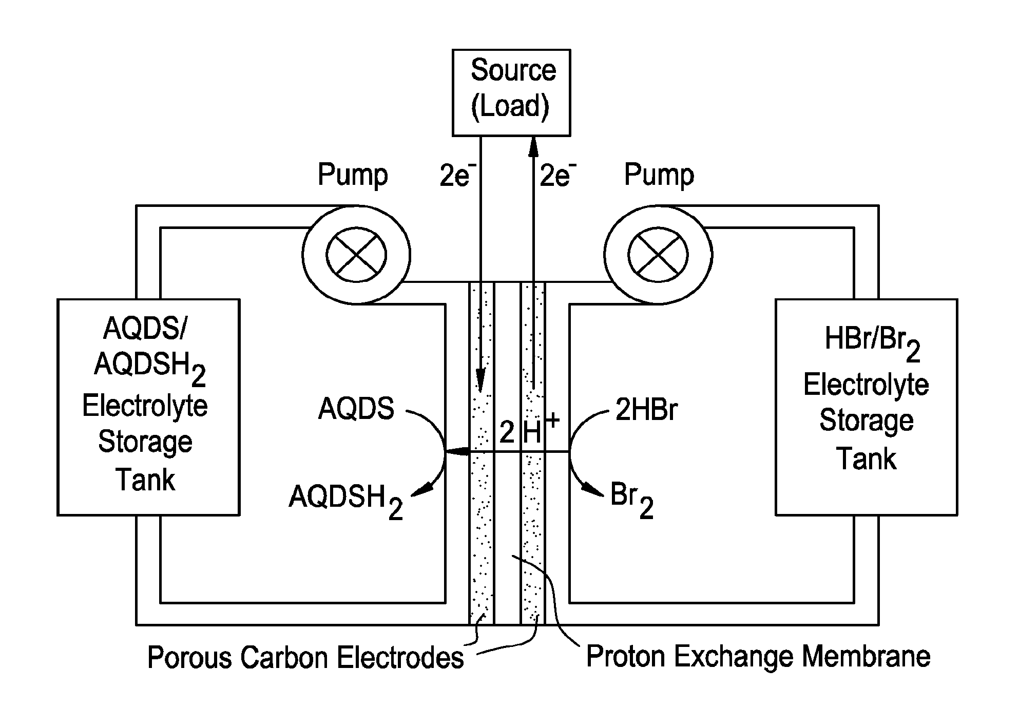
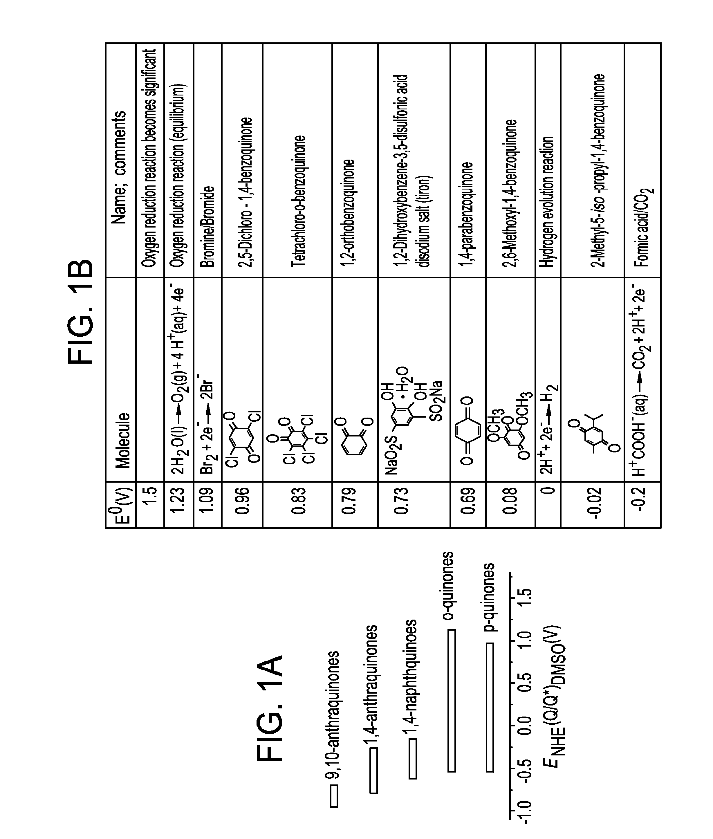
The invention provides an electrochemical cell based on a new chemistry for a flow battery for large scale, e.g., gridscale, electrical energy storage. The use of quinones, which are organic molecules, offers advantages over current flow batteries including scaling advantages, high current density, and long lifetime. The absence of active metal components in the redox chemistry and catalysis also reduces costs. The patent presents a new direction for cost-effective, large-scale energy storage.

Problems solved by technology

Stability is important not only to prevent chemical loss for long cycle life, but also because polymerization on the electrode can compromise the electrode's effectiveness.
Many quinones or hydroquinones are available commercially on a small scale, and their current market price sets an upper limit on what the price might be at large scale.
While the use of bromine is advantageous in many systems, use in a manned environment, such as the home, is limited based on toxicity concerns; therefore bromine-based systems are best focused on industrial and some commercial applications.

Method used


Image

  • Small organic molecule based flow battery
  • Small organic molecule based flow battery
  • Small organic molecule based flow battery

Examples


example 1

[0088]1 molal 1,2-ortho-benzohydroquinone (catechol) was oxidized in 1 N H2SO4 at a flat Pt electrode, obtaining the cyclic voltammetry curves shown in FIG. 3A. The sweep starts at (0.2 V, 0 mA / cm2) and proceeds at 25 mV / s to the right. At about 600 mV vs. Ag / AgCl (the known E0 is 795 mV vs. SHE), the current density increases as catechol is oxidized to the orthoquinone form. The oxidative current density peaks at about 150 mA / cm2. The peak and downturn are caused by reactant depletion in a quiescent (non-flowing, non-stirred) electrolyte. In a test at a higher concentration of 3.9 molal (FIG. 3B), we observe asymmetric oxidation and reduction peaks, achieving current densities above 500 mA / cm2 for the former. The asymmetric shape of the curve in FIG. 3B arises because the quinone form is unstable in aqueous solution. In addition the limited solubility of ortho-benzoquinone (0.06 M) compared to its reduced form precludes symmetric behavior at high concentration.

example 2

[0089]The half-cell redox behavior of hydroquinone-2-sulfonic acid (HQSA) is shown in FIG. 4. At a pH of 7 a rise in current density was observed beginning near 0.5 V and peaking at higher voltage. Upon reversing the direction of the voltage sweep, negative current (indicating a reduction event) was observed near 0.3 V. The large difference between where the oxidation and reduction currents are observed indicates a chemical process was likely occurring. In this case, upon oxidation of HQSA to the quinone form, water reacted with the quinone to form a new species. This species was reduced at the lower 0.3 V potential. At a pH of 13, the reaction became rapid and reversible because in basic solution the —OH groups on HQSA became deprotonated. The positive and negative current density observed near 0 V was indicative of a 2-electron redox event with no protons having been exchanged.

example 3

[0090]AQDS was subjected to half-cell electrochemical measurements. Cyclic voltammetry of a 1 mM solution of AQDS in 1 M sulfuric acid on a glassy carbon disc working electrode showed current peaks corresponding to reduction and oxidation of the anthraquinone species (FIG. 5A). The peak separation of 34 mV was close to the 59 mV / n, where n was the number of electrons involved, expected for a two-electron process.


PUM

PropertyMeasurementUnit
current densitiesaaaaaaaaaa
standard electrochemical potentialaaaaaaaaaa
current densitiesaaaaaaaaaa

Abstract

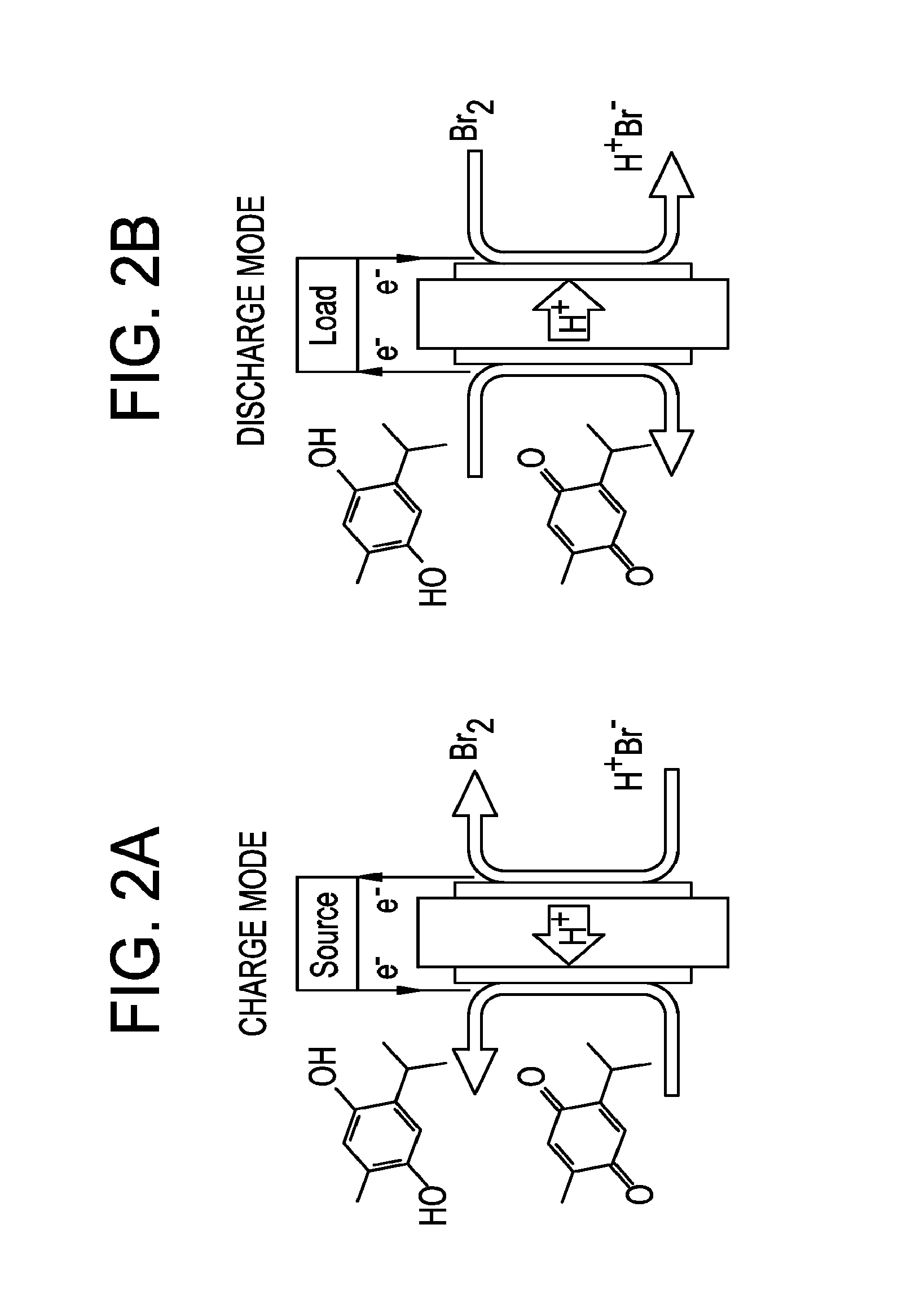
The invention provides an electrochemical cell based on a new chemistry for a flow battery for large scale, e.g., gridscale, electrical energy storage. Electrical energy is stored chemically at an electrochemical electrode by the protonation of small organic molecules called quinones to hydroquinones. The proton is provided by a complementary electrochemical reaction at the other electrode. These reactions are reversed to deliver electrical energy. A flow battery based on this concept can operate as a closed system. The flow battery architecture has scaling advantages over solid electrode batteries for large scale energy storage.

Description

STATEMENT REGARDING FEDERALLY SPONSORED RESEARCH[0001]This invention was made with government support under grant number DE-AR0000348 from the Advanced Research Projects Agency—Energy—U.S. Department of Energy. The government has certain rights to the invention.BACKGROUND OF THE INVENTION[0002]Intermittent renewable electrical power sources such as wind and photovoltaics (PV) cannot replace a significant fraction of our current fossil fuel-based electrical generation unless the intermittency problem is solved. Fluctuations in renewable source power are generally backed up by natural gas fired “peaker” plants. Inexpensive, reliable energy storage at or near the generation site could render the renewable source dispatchable (e.g. demand-following) and permit the gas peakers to replace baseload coal. It could also permit full utilization of the transmission capacity of power lines from the generation site, permitting supply capacity expansion while deferring the need for transmission c...

Claims


Application Information

Patent Timeline
Patent Type & Authority Applications(United States)
IPC IPC(8): H01M8/08H01M8/04H01M8/18H01M8/20
CPCH01M8/083H01M8/04186H01M2300/0014H01M8/20H01M8/188H01M4/9008H01M8/04201Y02E60/50H01M2300/0011H01M4/60
Inventor HUSKINSON, BRIANMARSHAK, MICHAELAZIZ, MICHAEL J.GORDON, ROY G.BETLEY, THEODORE A.ASPURU-GUZIK, ALANER, SULEYMANSUH, CHANGWON
Owner PRESIDENT & FELLOWS OF HARVARD COLLEGE
Learn More