
High chlorine content low attenuation optical fiber

a low attenuation, optical fiber technology, applied in the field of optical fibers, can solve the problems of glass relaxation, high draw induced stress in the core region, high viscosity of optical fibers, etc., and achieve the effects of reducing fiber attenuation, reducing fiber stress, and reducing viscosity

Active Publication Date: 2016-01-14
CORNING INC
View PDF2 Cites 38 Cited by
  • Summary
  • Abstract
  • Description
  • Claims
  • Application Information

AI Technical Summary

Benefits of technology

The patent describes optical waveguide fibers with a core made of silica and chlorine, which have a refractive index higher than that of the cladding. The fibers have a reduced viscosity mismatch and lower stresses, resulting in reduced attenuation and better performance. The fibers also have a cable cutoff less than 1260 nm and a modeled attenuation of 0.15 dB / Km at 1550 nm. The fiber designs have effective area larger than 70 μm2 and can be made using a method involving chlorine doping. The technical effects of the patent include improved optical properties and reduced fiber attenuation.

Problems solved by technology

However, the Raleigh scattering due to germania doping limits low fiber attenuation to about 0.18 dB / km for practical fibers due to Rayleigh scattering related to dopant concentration fluctuation.
However, these high silica content core optical fibers have high viscosity that increases the Rayleigh scattering due to high fictive temperature in the core.
In addition, the fluorine (F) doped cladding has a much lower viscosity, which results in high draw induced stress in the core region.
The high stress in the core region reduces the glass relaxation, which increases the Rayleigh scattering loss.
In addition, the stress effect reduces the core refractive index through stress-optic effects, making it difficult to achieve the core refractive index change required for making a single mode fiber, therefore even higher amounts (˜2×) of fluorine doping in the cladding is required.

Method used


Image

  • High chlorine content low attenuation optical fiber
  • High chlorine content low attenuation optical fiber
  • High chlorine content low attenuation optical fiber

Examples


example 1

[0045]A 1 meter long 3000 gram silica soot preform having a density of about 0.5 g / cm3 was prepared in a lathe by flame depositing silica soot onto 10 mm diameter removable alumina rotating bait rod comprising a silica handle. The soot preform was placed into a consolidation furnace and dried at about 1225° C. in an atmosphere comprising about 55 volume percent helium and about 45 volume percent SiCl4. The assembly was then traversed (down-driven) through a hot zone having a peak temperature of about 1500° C. at a temperature ramp rate of about 2.5° C. / min, thus producing a fully densified Cl-doped silica glass core preform.

[0046]This preform was placed for about 24 hours in an argon purged holding oven set at 1000° C. in order to outgas dissolved helium in the glass. The preform was then placed in a redraw furnace set at about 1900° C., vacuum was applied through the handle to the centerline portion of the preform to collapse the hole in the centerline, and the preform was redrawn ...

example 2

[0047]A 1 meter long 3000 gram silica soot preform having a density of about 0.5 g / cm3 was prepared in a lathe by flame depositing silica soot onto 10 mm diameter removable alumina rotating bait rod comprising a silica handle. The alumina bait rod was removed creating an open centerline hole in the preform (which comprised a silica handle), then an 8.5 mm core cane (comprising a 1.8 wt % Cl-doped silica core from Example 1) was inserted into the centerline hole of the soot preform producing a core-cane soot preform assembly.

[0048]The core-cane soot preform assembly was placed into a consolidation furnace and dried at about 1200° C. in an atmosphere comprising helium and about 2.5 volume percent chlorine. Following this step, the soot of the preform assembly was doped with fluorine for 1 hour in an atmosphere comprising helium and about 1 volume percent SiF4; then under these flow rates, the assembly was then traversed (down-driven) through a hot zone having a peak temperature of abo...

example 3

[0050]A 1 meter long 16 mm diameter cane from Example 2 was placed on a lathe, then about 3100 grams of silica soot was flame deposited on the cane producing a cane-overclad preform assembly having an overclad soot density of about 0.5 g / cm3. This assembly was placed into a consolidation furnace and dried at about 1200° C. in an atmosphere comprising helium and about 2.5 volume percent chlorine Following this step, the assembly was doped with fluorine for 1 hour in an atmosphere comprising helium and about 1 volume percent SiF4; then under these flow rates, the assembly was then traversed (down-driven) through a hot zone having a peak temperature of about 1500° C. at a temperature ramp rate of about 2.5° C. / min to fluorine dope the silica soot and collapse the silica soot onto the core cane. This produced a fully densified void-free glass optical fiber preform having a Cl-doped silica core, a fluorine-doped silica cladding and fluorine-doped silica overcladding.

[0051]This preform wa...


PUM

PropertyMeasurementUnit
Temperatureaaaaaaaaaa
Lengthaaaaaaaaaa
Percent by massaaaaaaaaaa

Abstract

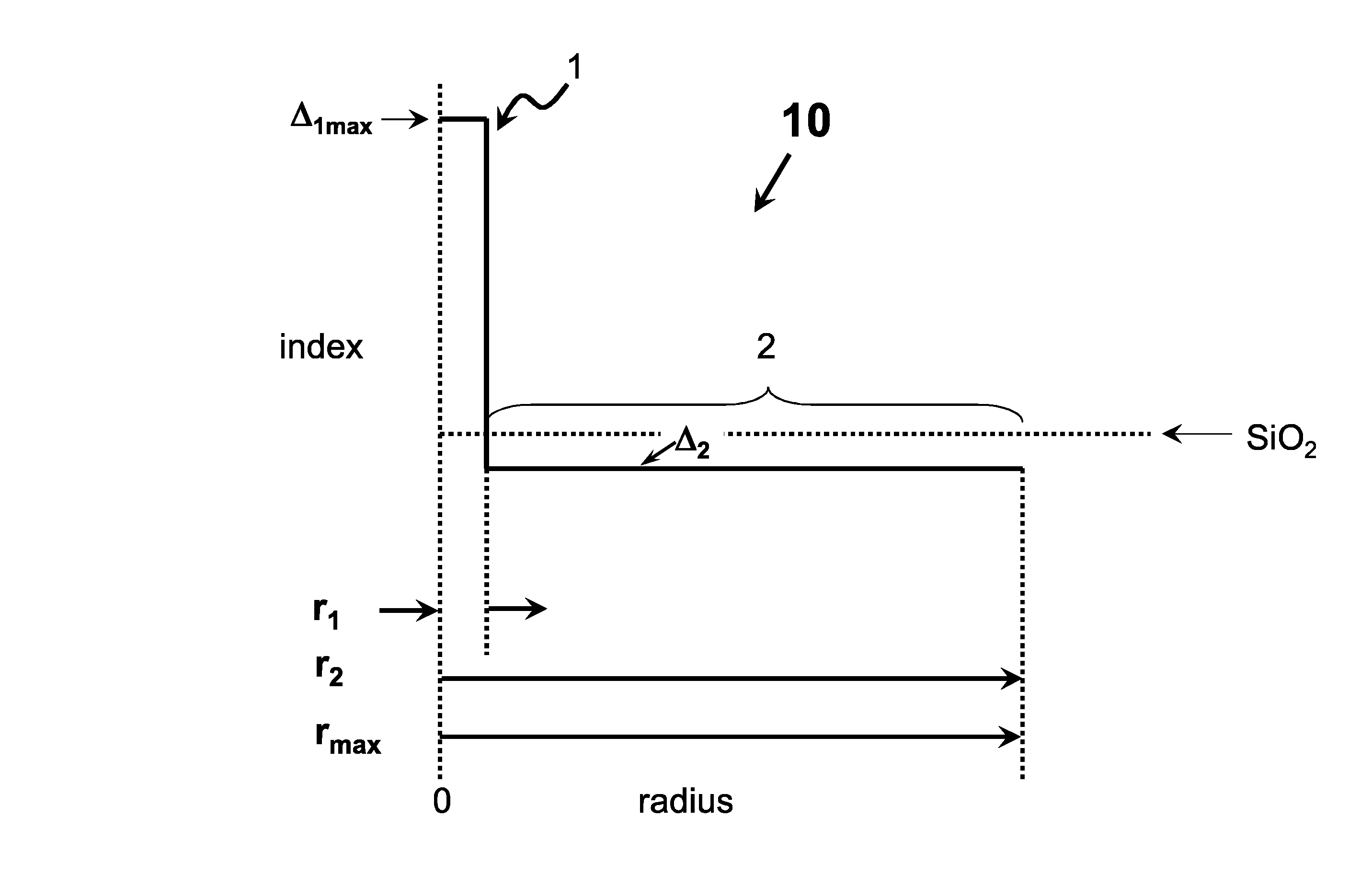
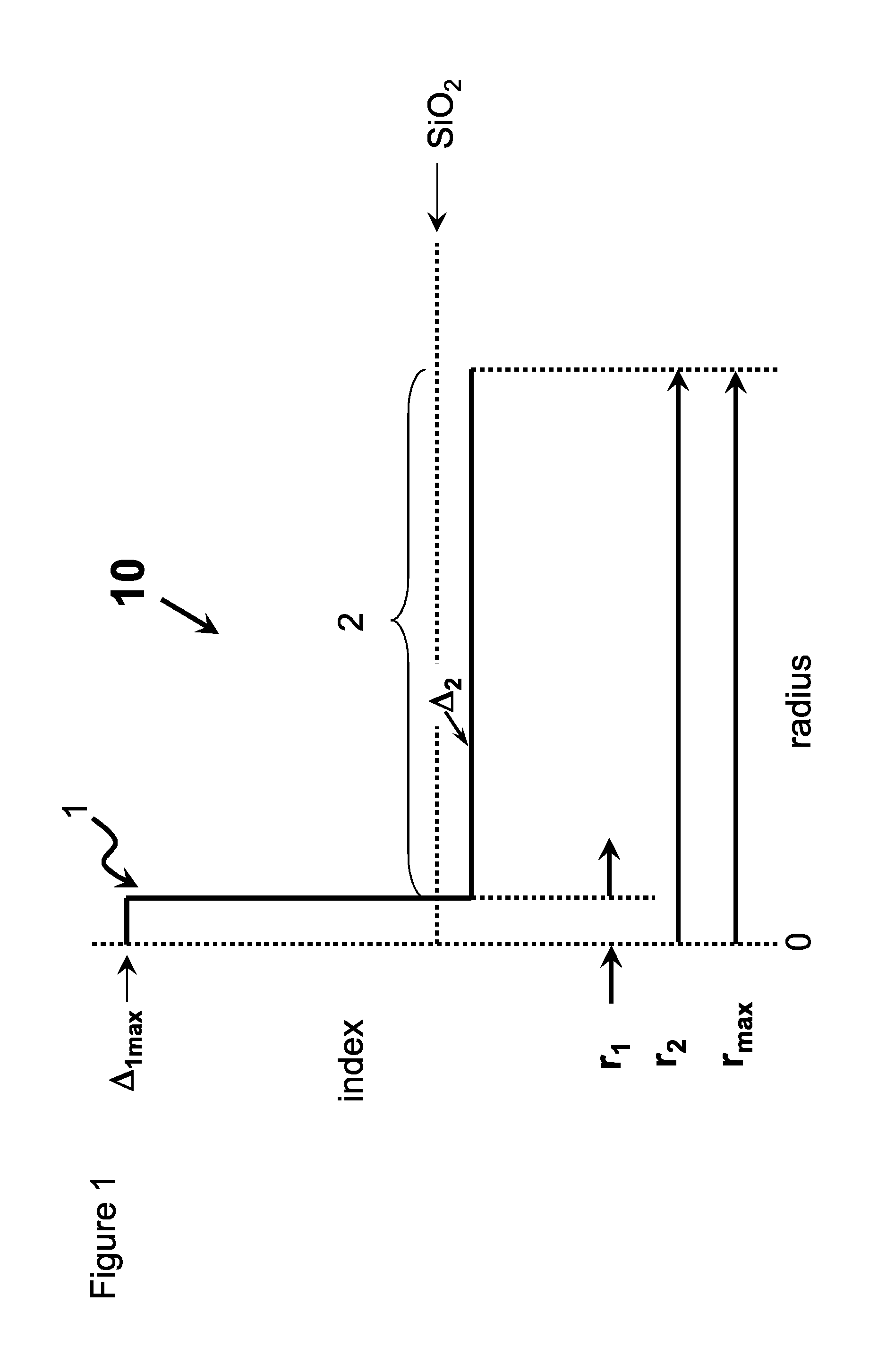
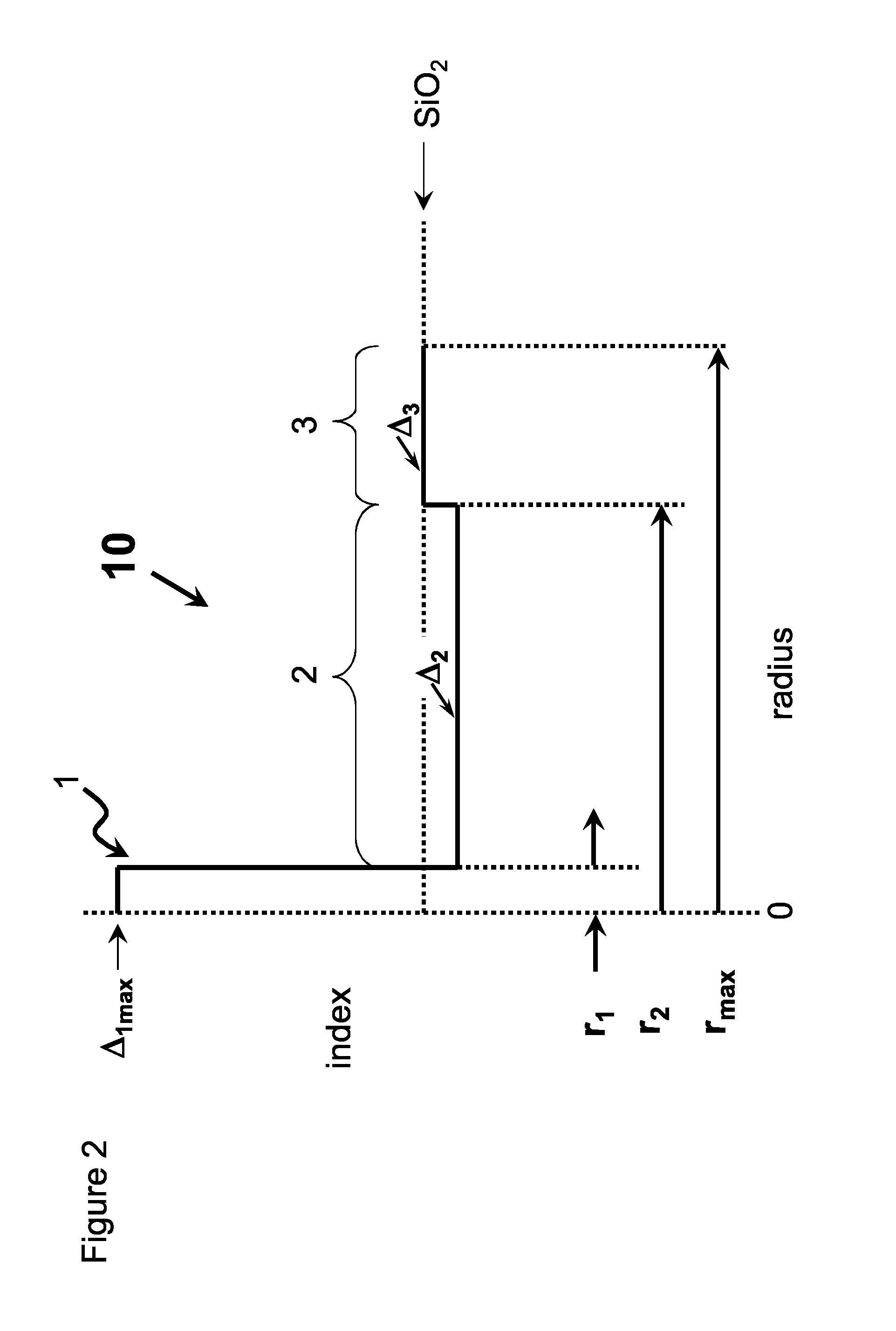
An optical fiber having a core comprising silica and greater than 1.5 wt % chlorine and less than 0.5 wt % F, said core having a refractive index Δ1MAX, and a inner cladding region having refractive index Δ2MIN surrounding the core, where Δ1MAX>Δ2MIN.

Description

[0001]This application claims the benefit of priority under 35 U.S.C. §119 of U.S. Provisional Application Ser. No. 62 / 022,926 filed on Jul. 10, 2014, the content of each is relied upon and incorporated herein by reference in its entirety.FIELD[0002]The present invention relates to optical fibers having high chlorine dopant levels in the core of the fiber.TECHNICAL BACKGROUND[0003]There is a continuing need for lower attenuation optical fibers. Low attenuation is one of the most critical properties in optical fibers. Most optical fibers use germania (GeO2) doped silica for the core region and pure silica for the overclad region. However, the Raleigh scattering due to germania doping limits low fiber attenuation to about 0.18 dB / km for practical fibers due to Rayleigh scattering related to dopant concentration fluctuation. To reduce dopant concentration fluctuation, relatively high silica core fibers have been made which utilize a fluorine doped cladding. These fibers sometimes inclu...

Claims


Application Information

Patent Timeline
IPC IPC(8): G02B6/02C03B37/012C03B37/018G02B6/036
CPCG02B6/02014G02B6/02019G02B6/03627C03B2201/20C03B37/01853C03B37/018C03B2201/08C03B37/01205C03C25/1061C03B37/01211C03B37/01262C03B37/01282C03B37/01413C03B37/01433C03B37/01446C03B37/01838C03C13/045C03B2207/30C03B2205/42C03B2203/23C03B2203/24C03B2201/12C03C2203/54C03C2201/11C03C2201/12C03C13/04C03B37/01453C03B37/01815C03B37/0183C03B37/01869C03B2201/24C03B2203/22C03C13/046C03C2213/00
Inventor BERKEY, GEORGE EDWARDBOOKBINDER, DANA CRAIGLI, MING-JUNTANDON, PUSHKAR
Owner CORNING INC
Learn More