Supercharge Your Innovation With Domain-Expert AI Agents!

Anti-Islanding Detection for Three-Phase Distributed Generation

a technology of distributed generation and detection, applied in the direction of electric variable regulation, process and machine control, instruments, etc., can solve the problems of increasing the initial capital expenditure required, increasing the capacity, and inherently limited power generation capacity of the generation facility, so as to achieve the effect of reliably distinguishing between islanding events

Active Publication Date: 2014-07-31
VIRGINIA TECH INTPROP INC
View PDF4 Cites 14 Cited by
  • Summary
  • Abstract
  • Description
  • Claims
  • Application Information

AI Technical Summary

Benefits of technology

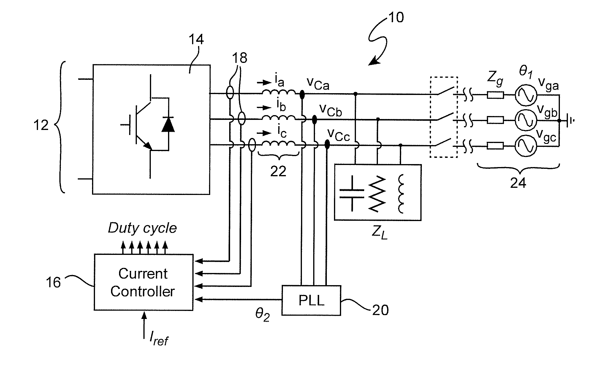
[0049]To better understand this function which supports an important meritorious effect of the invention, reference is now made to FIGS. 10-12 and a comparison of FIGS. 9 and 10 to FIGS. 7 and 8 may be helpful, as well. Specifically, the PLL of FIG. 9 can be modeled as illustrated in FIG. 10 in which the upper, negative and lower, positive feedback loops, as discussed above in connection with FIG. 8 are evident. The notation sin( ) shown in the control block represents the sine function” if the input and output of the control block are x and y, respectively, then the relationship is y=sin x. As noted above, when the PLL is grid-connected, the upper, negative feedback loop is dominant (since k is small compared to θ1 and p1) and the depiction of FIG. 10 reduces to the model illustrated in FIG. 11 which accurately tracks the phase information from the grid. Conversely, in the islanded condition, upper, negative feedback loop effectively vanishes and the converter frequency varies with k (e.g. p2−k); following the variation of the input injection signal.
[0050]The response of the PLL of FIG. 10 under grid connected and islanded conditions is illustrated in FIG. 13 illustrating PLL frequency as a function of time. If only considering the proportional gain Kp in the PLL, but not the effect of the triangular wave, the output frequency will be constant at 2π60 rad / sec as shown at 132. If considering only the effects of Kp and the triangular waveform (also sometimes referred to simply as k in reference to the gain shown in FIG. 9) the frequency will vary with k but will not drift over time; returning to 2π60 when the triangular waveform returns to zero as shown at 134. A larger k will cause more frequency variation and a more sharply angled frequency waveform. If both Kp and integrator Ki are considered, Ki will allow the varying frequency to drift downward as shown at 136. This frequency variation and drift are effectively a perturbation which will cause the lower, positive feedback loop to drive the converter frequency away from 2π60 unconditionally and within a very short period after islanding occurs. In FIG. 13, the change in K2 and p2 in terms of w2 are not considered since they are generally very small within the first two seconds or cycles of k, especially if the quality factor, Q=R*sqrt(C / L), of the resonant load is very small. If Q is large, the effect of K2 and p2 can be calculated.
[0051]It is important to note that the period of the variation of k in FIG. 13 is about 1.0 seconds or less, as is preferred. Under such conditions at least one peak in the frequency will occur within two seconds of an islanding event; the time limit specified in the IEEE standard. Thus the frequency of the PLL output can be monitored and islanding can be reliably detected based on either of two conditions illustrated in FIG. 14. Specifically, when k reaches a maximum, kmax, the frequency can be compared with 60 Hz and, if the difference is above a threshold, islanding can be determined to have occurred. Similarly, when k reaches kmax, the frequency can be compared with the frequency when k=0 and if the difference is greater than a threshold (e.g. the frequency variation due to variation in k plus a small tolerance) islanding can also be determined to have occurred.
[0052]Simulation result for a load of 10Ω+600 μf+11.5 mH is shown in FIG. 15 which indicates that the output frequency of the PLL will follow a small signal k having a peak value of only 200μ (since this is a gain of a control signal, there are no physical units) and thus the islanding condition can be easily detected with only a negligible effect on the PLL when grid connected. The experimental results shown in FIG. 16 agree well with the simulation results with the same / / RCL load resonant at 60 Hz.
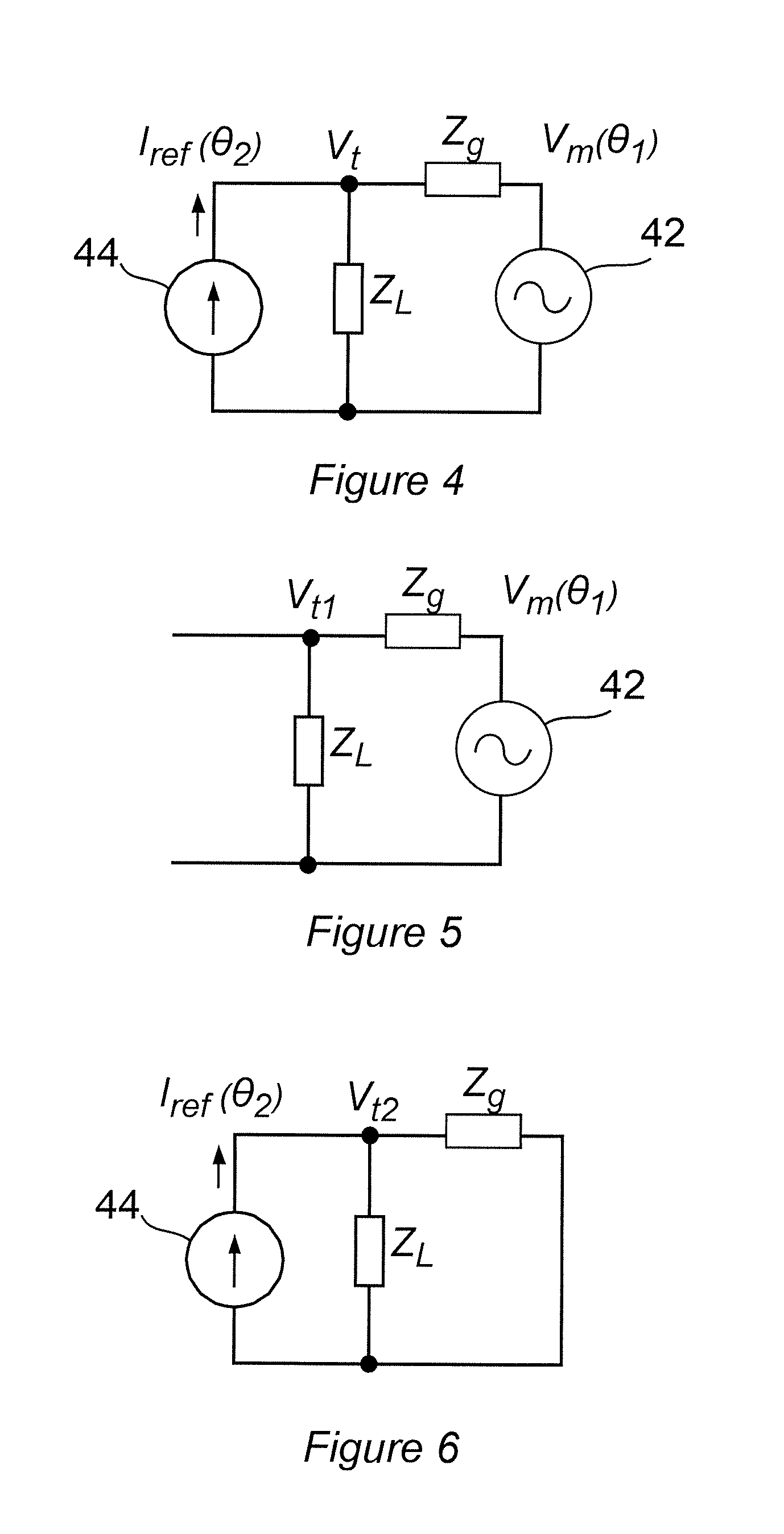
[0053]The islanding detection technique, PLL and algorithm of the first embodiment can be shown to not violate the LVRT requirements of the IEEE standard. That is, low voltage grid conditions should not be detected as an islanding event. The test circuit for determining if this condition is met is illustrated in FIG. 17, as specified in the IEEE standard. Essentially, this test circuit inserts a switched small shunt impedance, Z2 to simulate the low voltage condition. The corresponding one-line equivalent circuit diagram is illustrated in FIG. 18. Based on the equivalent circuit of FIG. 18, the parameters of the generic PLL model are given by the equations:{K1=Zs / / ZLZs / / ZL+ZgK2=(Zs / / ZL)ZgZs / / ZL+Zg(9){p1=phase[Zs / / ZLZs / / ZL+Zg]p2=phase[(Zs / / ZL)ZgZs / / ZL+Zg](10)
[0054]Thus it is seen from equation 10 that the ratio of K1 and K2 does not change under the low voltage condition and there is only a small change in the phase shift term p2. Therefore, if the grid is a reasonably stiff grid with Zg near zero, low voltage conditions will not be detected as an islanding condition or event. A simulation of low voltage conditions is graphically illustrated in FIG. 19 with Zg and Zs, shown in FIG. 18 chosen to be 0.56 p.u. (a relatively large value) and 0.056 per unit (p.u.) impedance, only the relative value being important in regard to a power system representing a vary weak grid; a substantially worst case. FIG. 19 shows that the PLL is stable during the low voltage period.

Problems solved by technology

All such power generation facilities inherently have limited power generation capacity although that capacity may be quite large.
At the same time, greater power generation capacity of a given facility may greatly increase the initial capital expenditure required as well as possibly increasing cost of maintenance over the service life of power generation equipment.
Such a disconnection, sometimes referred to as grid loss, can rapidly cause significant damage to local loads and local power converters must be rapidly shut down when a disconnection is detected to prevent or mitigate such damage.
The main drawback of passive islanding detection schemes is exhibiting different NDZ regions.
In particular, no passive islanding detection arrangement can detect islanding when the load matches the output active power of the converter at the same resonant frequency as the line frequency of the grid.
However, suitable positive feedback mechanisms and characteristics and design procedures for such methods are not well-developed at the present time and over-design or excessive experimentation have often been required to meet the islanding detection standard.
While approaches to islanding detection have recently been the subject of substantial study, few studies have considered the impact of OFIDs on power converter operation, entire system stability or performance of sophisticated power systems such as multi-converter systems.
None of the known OFID approaches have, to date, achieved a robust zero NDZ.

Method used


Image

  • Anti-Islanding Detection for Three-Phase Distributed Generation
  • Anti-Islanding Detection for Three-Phase Distributed Generation
  • Anti-Islanding Detection for Three-Phase Distributed Generation

Examples


Embodiment Construction

[0038]Referring now to the drawings, and more particularly to FIG. 1, there is shown a schematic representation of a three-phase grid interface PWM converter system 10 to which the invention can be applied and with which the invention has particular utility. It should be understood that other types of power converters can be used and that the power converters can be of any known or foreseeable topology. It should also be understood that FIG. 1 is arranged to illustrate application of the invention to a multi-phase power generation system. Thus, at the level of abstraction of the illustration of FIG. 1, the invention may or may not be illustrated. Therefore, no portion of FIG. 1 is admitted to be prior art in regard to the present invention.

[0039]As alluded to above, most smaller power generation systems (e.g. under the 10 MW capacity to which the above standard is applicable) receive power as direct current (DC) at a relatively constant voltage, as depicted by bracket 12 which could...


PUM


Abstract

Wobbling the operating frequency of a phase-locked loop (PLL), preferably by adding a periodic variation is feedback gain or delay in reference signal phase allows the avoidance of any non-detection zone that might occur due to exact synchronization of the phase locked loop operating frequency with a reference signal. If the change in PLL operating frequency is periodic, it can be made of adequate speed variation to accommodate and time requirement for islanding detection or the like when a reference signal being tracked by the PLL is lost. Such wobbling of the PLL operating frequency is preferably achieved by addition a periodic variable gain in a feedback loop and / or adding a periodically varying phase delay in a reference signal and / or PLL output.

Description

CROSS-REFERENCE TO RELATED APPLICATIONS[0001]This application claims benefit of priority of U.S. Provisional Application 61 / 758,381, filed Jan. 30, 2013, which is hereby incorporated by reference in its entirety. The present invention is also related to U.S. patent application Ser. No. 13 / 910,371, filed Jun. 5, 2013, Which is also hereby incorporated by reference in its entirety.FIELD OF THE INVENTION[0002]The present invention generally relates to distributed power generation and distribution systems and, more particularly, to islanding detection for a distributed power generation system and converter.BACKGROUND OF THE INVENTION[0003]At the present time, electrical power is available to virtually all people in most civilized countries of the world. Consumers of such electrical power are often distributed over a wide geographic area while power generation facilities are generally located in the proximity of either a fuel or energy source (e.g. hydroelectric facilities are often loca...

Claims


Application Information

Patent Timeline
IPC IPC(8): H03L7/10H02M1/08
CPCH02M1/08H03L7/104H03L7/08H02J3/40H02J3/38H02J3/388
Inventor DONG, DONGBOROYEVICH, DUSHANMATTAVELLI, PAOLO
Owner VIRGINIA TECH INTPROP INC
Features
  • R&D
  • Intellectual Property
  • Life Sciences
  • Materials
  • Tech Scout
  • Unparalleled Data Quality
  • Higher Quality Content
  • 60% Fewer Hallucinations
Learn More