Chemical Vapor Deposition System

a chemical vapor and vapor deposition technology, applied in chemical vapor deposition coating, coating, metallic material coating process, etc., can solve the problems of large and undesirable lattice strain in the gan layer, complex deposition of gan on si substrate, large etch pit in the si substrate, etc., to reduce stress and improve the effect of stress

Inactive Publication Date: 2014-05-08
INTERMOLECULAR
View PDF25 Cites 10 Cited by
  • Summary
  • Abstract
  • Description
  • Claims
  • Application Information

AI Technical Summary

Benefits of technology

[0135]The systems and methods of the present invention allow the formation of layers both by CVD processes involving the simultaneous provision of two or more precursor gases to a surface for reactive deposition, and by processes that combine CVD deposition and a sequential plasma treatment in a cyclic fashion. The cyclic deposition process, in which the gases used in the CVD deposition are separated from the gases in the plasma, eliminates problems associated with reactive CVD and PECVD. In particular, the present systems and methods reduce (1) dust formation due to the ionization of metal organic precursors and the interaction of metal-organic precursors with the reactive species in the plasma or second precursor gas, and (2) chamber wall coating due to the same gas phase interaction between metal-organic precursors with the reactive species in the plasma or precursor gas. The reduction in dust formation results in superior films with fewer particles and defects, an important aspect for microelectronics, photovoltaics, optoelectronics (e.g., LEDs) and optically transparent coatings. The reduction in chamber wall coating reduces the need for chamber cleaning periodic maintenance and chamber cleaning chemistries (which are often toxic and damaging to the chamber hardware and pumps).
[0136]In addition, some embodiments of the present invention provide improved methods for forming layers on substrates. In particular, wafer stress can result from treatment of substrates to deposit layers at high temperatures. Wafer bowing can result from lattice mismatch between substrate surface and layers formed thereon due to differences in thermal expansion. The inventive systems and methods described herein using plasmas in conjunction with chemical vapor deposition can ameliorate these stresses by providing effective layer deposition in the absence of high thermal activation required with conventional MOCVD. Plasma energy can provide nonthermal energy to aid in formation of layers, thereby reducing stresses due to high heat exposures. Thus, the inventive approaches provide greater ability to tailor the surface energy during the growth of a layer, to control the resulting texture of the surface, the growth rate, the growth temperature, and the impurity levels in the film.
[0137]Methods and systems of embodiments of the invention may be combined with, or modified by, other systems and methods. For example, methods and systems of embodiments of the invention may be combined with, or modified by, methods and systems described in U.S. Pat. No. 6,305,314, U.S. Pat. No. 6,451,695, U.S. Pat. No. 6,015,590, U.S. Pat. No. 5,366,555, U.S. Pat. No. 5,916,365, U.S. Pat. No. 6,342,277, U.S. Pat. No. 6,197,683, U.S. Pat. No. 7,192,849, U.S. Pat. No. 7,537,950, U.S. Pat. No. 7,326,963, U.S. Pat. No. 7,491,626, U.S. Pat. No. 6,756,318, U.S. Pat. No. 6,001,173, U.S. Pat. No. 6,856,005, U.S. Pat. No. 6,869,641, U.S. Pat. No. 7,348,606, U.S. Pat. No. 6,878,593, U.S. Pat. No. 6,764,888, U.S. Pat. No. 6,690,042, U.S. Pat. No. 4,616,248, U.S. Pat. No. 4,614,961, U.S. Pat. No. 8,143,147, U.S. Patent Publication No. 2006 / 0021574, U.S. Patent Publication No. 2007 / 0141258, U.S. Patent Publication No. 2007 / 0186853, U.S. Patent Publication No. 2007 / 0215036, U.S. Patent Publication No. 2007 / 0218701, U.S. Patent Publication No. 2008 / 0173735, U.S. Patent Publication No. 2009 / 0090984, U.S. Patent Publication No. 2010 / 0210067, Patent Cooperation Treaty (“PCT”) Publication No. WO / 2003 / 041141, PCT Publication No. WO / 2006 / 034540 and PCT Publication No. WO / 2010 / 091470, and PCT Publication No. WO / 2010 / 092482, which are entirely incorporated herein by reference.

Problems solved by technology

However, the deposition of GaN on Si substrates is complicated by the need for an adequate buffer layer between the Si substrate and the GaN.
The buffer layer is needed because free Ga present on the Si surface during the initial stages of GaN growth directly on Si results in undesirable etch pits in the Si substrate.
Additionally, there is a poor lattice match between GaN and Si that results in large and undesirable lattice strain in deposited GaN layers.
However, the high processing temperature necessary to deposit AlN layers, typically 1200° C. or greater to form c-axis oriented AlN, makes AlN deposition challenging.
While methods exist for forming InGaAlN films, there are limitations associated with current methods.
First, the high processing temperature involved in MOCVD may require complex reactor designs and the use of refractory materials and only materials which are inert at the high temperature of the process in the processing volume.
Second, the high temperature involved may restrict the possible substrates for InGaAlN growths to substrates which are chemically and mechanically stable at the growth temperatures and chemical environment, typically sapphire and silicon carbide substrates.
Notably, silicon substrates, which are less expensive and are available in large sizes for economic manufacturing, may be less compatible.
Third, the expense of the process gases involved as well as their poor consumption ratio, particularly in the case of ammonia, may be economically unfavorable for low cost manufacturing of InGaAlN based devices.
Fourth, the use of carbon containing precursors (e.g., trimethylgallium) may result in carbon contamination in the InGaAlN film, which may degrade the electronic and optoelectronic properties of the InGaAlN based devices.
Fifth, MOCVD reactors may result in a significant amount of gas phase reactions between the Group III and the Group V containing process gases, leading to the undesirable deposition of the thin film material on all surfaces within the reaction volume, and in the undesirable generation of particles, as well as inefficient loss of reactants.
The latter may result in a low yield of manufactured devices.
The former may result in a number of practical problems, including reducing the efficacy of in situ optical measurements of the growing thin film due to coating of the internal optical probes and lens systems, and difficulty in maintaining a constant thermal environment over many deposition cycles as the emissivity of reactor walls will change as deposition builds up on the reactor walls.
The method may be capable of producing high quality InGaAlN thin films and devices, but the method may suffer from a tendency to form metal agglomerations, e.g., nano- to microscopic Ga droplets, on the surface of the growing film.
As such, the process may need to be carefully monitored, which may inherently result in a low yield of manufactured devices.
The method may require corrosive chemicals to be used at high temperatures, which may limit the compatible materials for reactor design.
In addition, the byproducts of the reaction are corrosive gases and solids, which may increase the need for abatement and reactor maintenance.
While the method may produce high quality GaN films at growth rates (tens to hundreds of microns per hour have been demonstrated, exceeding those commonly achieved with MOCVD), the reactor design and corrosive process inputs and outputs are drawbacks.
PECVD suffers from excessive gas phase reactions and dust generation due to the interaction of the charged species in the plasma with the precursors for the deposition.
It is not currently accepted as a manufacturing solution for LEDs for white lighting applications or for power electronics.
However, the process is time consuming and inefficient since the chamber must be evacuated between each reaction cycle.
However, the described process limits coverage to one monolayer per exposure and use of purge gas compartments to separate the source gas compartments and plasma chamber.

Method used


Image

  • Chemical Vapor Deposition System
  • Chemical Vapor Deposition System
  • Chemical Vapor Deposition System

Examples


example 1

Preparation of AlN Layers

[0138]Si(111) wafers were prepared by a two-step cleaning process. The wafers were boiled in an aqueous solution of HCl and H2O2, rinsed and dried, then etched in 20% HF. AlN was grown on the Si wafers by first exposing the wafers to trimethylaluminum at a pressure of about 0.5 Torr and a wafer temperature of 700-900° C. About 0.5 ML of Al was formed on the surface which was then exposed to a N2 plasma at 500 W. The plasma power was sufficient to generate active neutral species of nitrogen having the lowest excited state of molecular nitrogen (A3Σu+). The exposure to excited species of N2 was sufficient to produce a layer of aluminum nitride on the surface of the substrate.

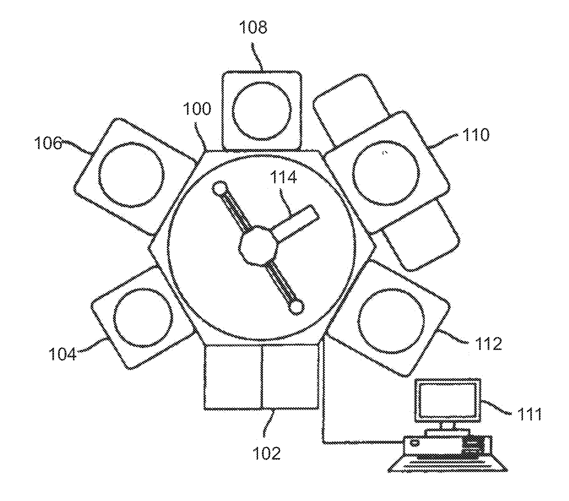
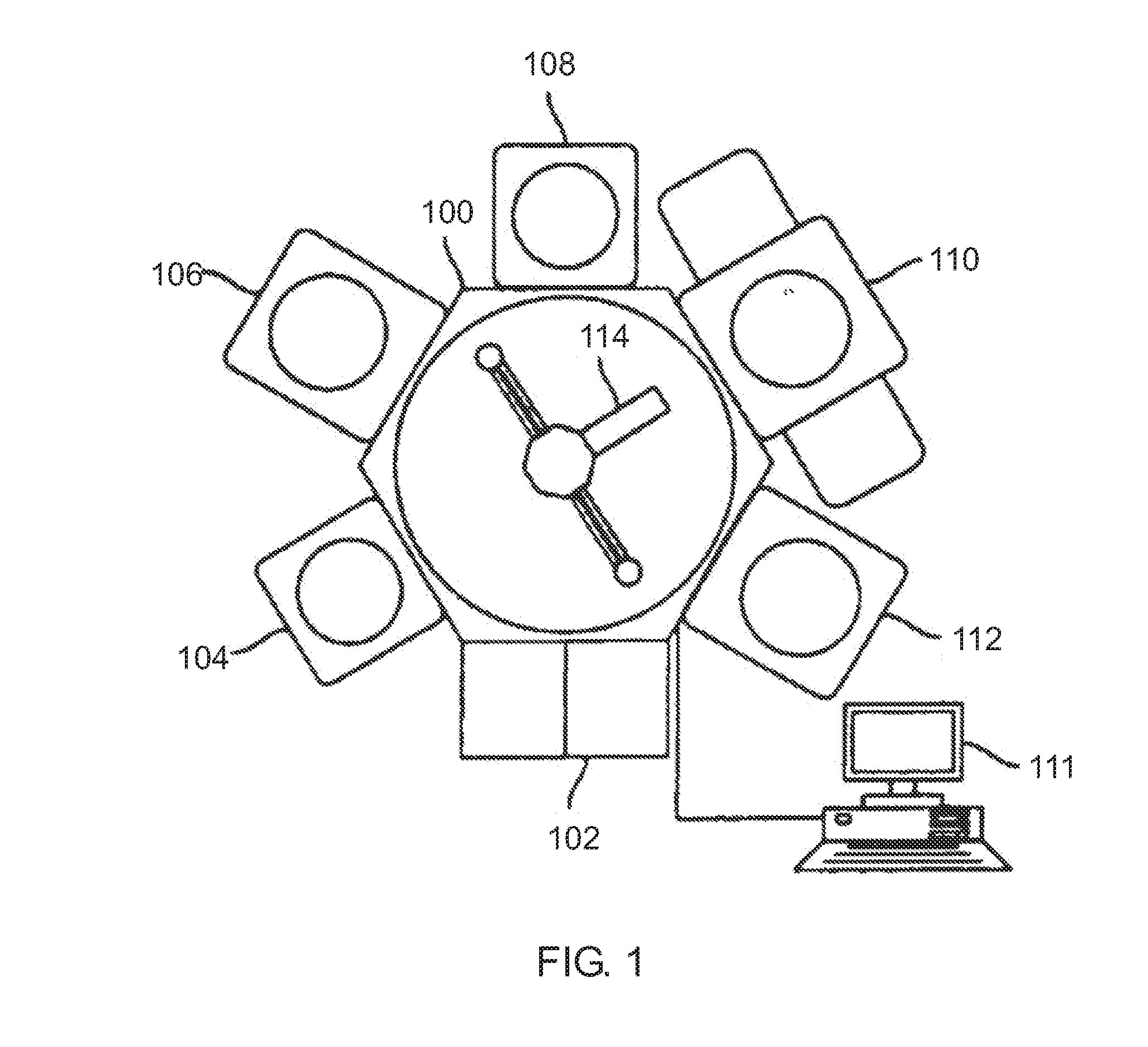
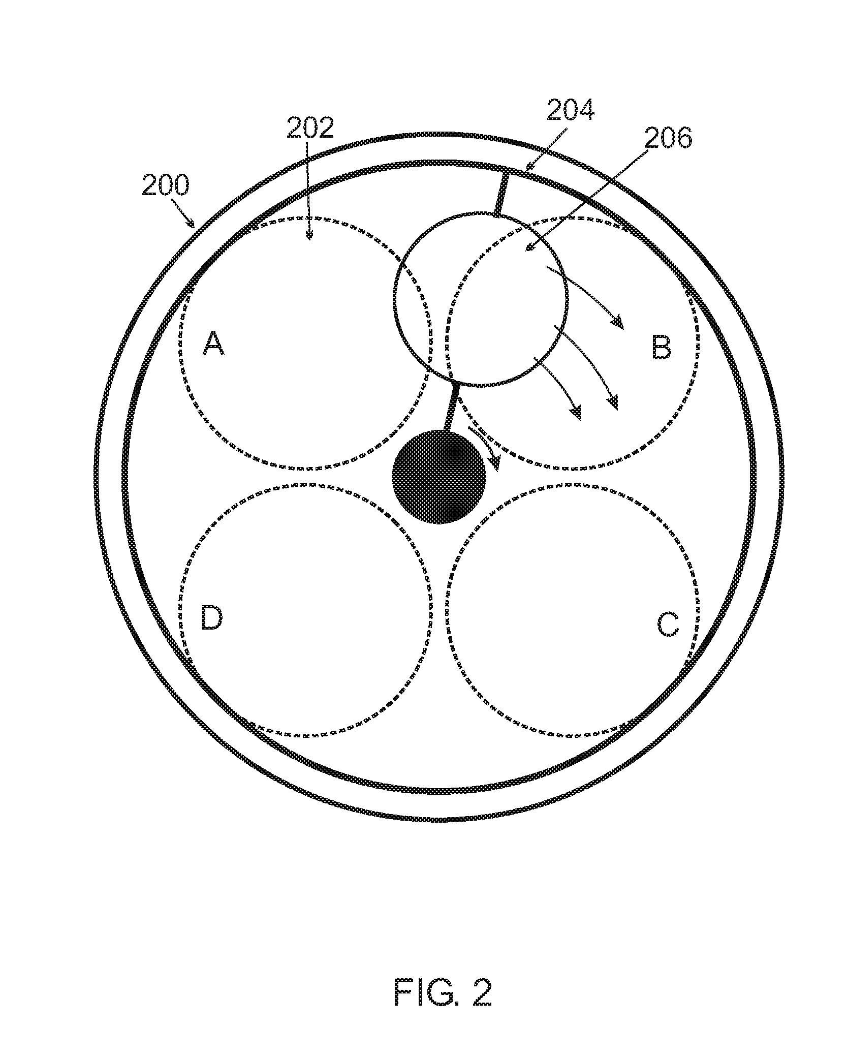
[0139]In this example, the wafer was continuously rotating between the chemical vapor deposition environment and the plasma environment to provide alternating exposures to the environments. The net growth rate of AlN was 1.2 μm / hr, and a 0.62 μm film was deposited in about 30 min as measur...

example 2

Preparation of AlN / AlGaN layers

[0140]AlN / AlGaN bilayers were deposited in the same apparatus by a similar process to that described in Example 1. A thin (100 nm) layer of AlN was first grown as described above followed by an AlGaN layer. The bilayer was produced in a continuous process by adding triethylgallium to the CVD environment after treatment for 340 seconds using only trimethylaluminum. The mole ratio of gallium to aluminum was 1:1. A total layer thickness of 0.68 μm was deposited at a rate of 1.7 μm / hr.

[0141]XRD analysis indicated that both the AlN layer and the AlGaN layer were hexagonal and c-axis oriented. The actual composition of the deposited layer was found to be AlxGa1-xN, where x=0.4. Surface roughness measured by AFM was 7.9 nm (rms) and the typical column width was about 25 nm.

[0142]These results confirmed that high quality AlN and AlGaN films could be formed using the apparatuses and methods of the instant invention at low temperature (compared to the more than ...


PUM

PropertyMeasurementUnit
pressureaaaaaaaaaa
temperatureaaaaaaaaaa
temperaturesaaaaaaaaaa

Abstract

Chemical vapor deposition (CVD) systems for forming layers on a substrate are disclosed. Embodiments of the system comprise at least two processing chambers that may be linked in a cluster tool. A first processing chamber provides a chamber having a controlled environmental temperature and pressure and containing a first environment for performing CVD on a substrate, and a second environment for contacting the substrate with a plasma; a substrate transport system capable of positioning a substrate for sequential processing in each environment, and a gas control system capable of maintaining isolation. A second processing chamber provides a CVD system. Methods of forming layers on a substrate comprise forming one or more layers in each processing chamber. The systems and methods are suitable for preparing Group III-V, Group II-VI or Group IV thin film devices.

Description

CROSS REFERENCE TO RELATED APPLICATIONS[0001]This is a Continuation Application of U.S. patent application Ser. No. 13 / 670,269, filed on Nov. 6, 2012, which is herein incorporated by reference for all purposes. This application is related to commonly owned U.S. patent application Ser. No. 13 / 546,672 and commonly owned U.S. patent application Ser. No. 13 / 025,046 now U.S. Pat. No. 8,143,147, which are herein incorporated by reference for all purposes. This application is also related to commonly owned co-pending U.S. patent application Ser. No. 13 / 398,663 (filed on Feb. 16, 2012) and Ser. No. 13 / 398,988 (filed on Feb. 17, 2012) which claim the benefit of Ser. No. 13 / 025,046, each of which are herein incorporated by reference for all purposes.FIELD OF THE INVENTION[0002]One or more embodiments of the present invention relate to methods and apparatuses for practicing chemical vapor deposition.BACKGROUND[0003]The growth of high-quality crystalline semiconducting thin films is a technolog...

Claims


Application Information

Patent Timeline
Patent Type & Authority Applications(United States)
IPC IPC(8): H01L21/02
CPCH01L21/0254C23C16/0227C23C16/303C23C16/305C23C16/409C23C16/45527C23C16/45534C23C16/45542C23C16/45551
Inventor KRAUS, PHILIPBORISOV, BORISCHUA, THAI CHENGNIJHAWAN, SANDEEP
Owner INTERMOLECULAR
Why Eureka
Try Eureka