
Conductive member, production method of the same, touch panel, and solar cell

Inactive Publication Date: 2014-02-06
FUJIFILM CORP
View PDF0 Cites 16 Cited by
  • Summary
  • Abstract
  • Description
  • Claims
  • Application Information

AI Technical Summary

Benefits of technology

The invention provides a conductive member that is very durable, can conduct electricity well, and is transparent, heat-resistant, and bendable. Additionally, the patent describes a method to make this conductive member, as well as some possible applications of it, like touch panels and solar cells.

Problems solved by technology

However, when an attempt was made to reduce scratches and abrasion in the conductive layer by providing the hard coat, it was necessary to provide the hard coat as thick as approximately from 1 μm to 50 μm, and there was a problem in that the conduction decreased.
On the other hand, in a case in which a hard coat thin enough to allow only a slight decrease in the conduction is provided, the hard coat could not sufficiently prevent scratches and abrasion in the conductive layer.
Furthermore, even in conductive members provided with a protective layer including a photocurable acrylic resin cured by UV on the surface of the conductive layer, scratches and abrasion in the conductive layer could not be sufficiently prevented, and, furthermore, the protective layer was not satisfactory in terms of heat resistance, moisture and heat resistance, and bendability.
As such, in conductive members having a conductive layer including a conductive fiber, it was difficult to reduce scratches and abrasion in the conductive layer and maintain a high conduction at the same time, and there was a demand for conductive members that satisfy both requirements.

Method used


Image

  • Conductive member, production method of the same, touch panel, and solar cell
  • Conductive member, production method of the same, touch panel, and solar cell
  • Conductive member, production method of the same, touch panel, and solar cell

Examples


synthesis example 1

[0367]

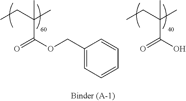
[0368]AA (9.64 g) and BzMA (35.36 g) were used as monomer components that form a copolymer, AIBN (0.5 g) was used as a radical polymerization initiator, and AA, BzMA and AIBN were made to cause a polymerization reaction in a solvent PGMEA (55.00 g), thereby obtaining a PGMEA solution (solid content concentration: 45% by mass) of a binder (A-1). Meanwhile, the polymerization temperature was adjusted to a temperature of from 60° C. to 100° C.

[0369]As a result of measuring the molecular weight using gel permeation chromatography (GPC), the weight average molecular weight (Mw) in terms of polystyrene was 11,000, the molecular weight distribution (Mw / Mn) was 1.72, and the acid value was 155 mgKOH / g.

synthesis example 2

[0370]

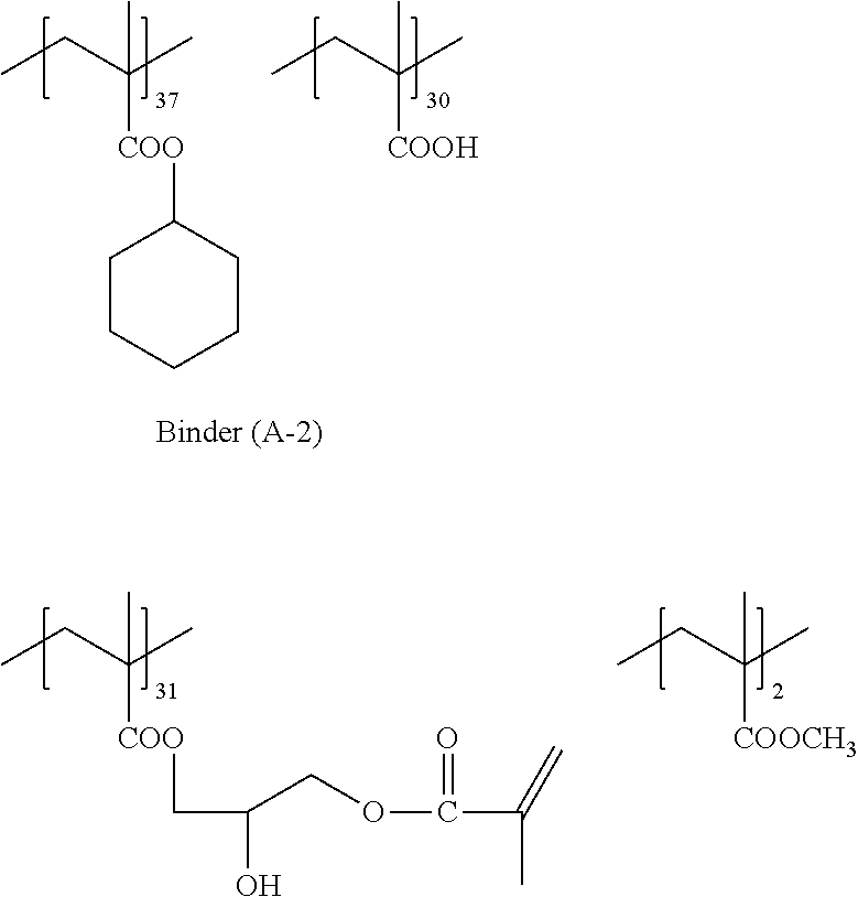
[0371]MFG (7.48 g, manufactured by NIPPON NYUKAZAI Co., Ltd.) was added in advance to a reaction container, heated to 90° C., and a solution mixture made up of MAA (14.65 g), MMA (0.54 g) and CHMA (17.55 g) as monomer components, AIBN (0.50 g) as a radical polymerization initiator and MFG (55.2 g) was added dropwise to the reaction container in a nitrogen gas atmosphere at 90° C. over 2 hours. After the dropwise addition, the components were reacted for 4 hours, thereby obtaining an acrylic resin solution.

[0372]Next, hydroquinone monomethyl ether (0.15 g) and tetraethylammonium bromide (0.34 g) were added to the obtained acrylic resin solution, and then GMA (12.26 g) were added dropwise over 2 hours. After the dropwise addition, the components were reacted for 4 hours at 90° C. while blowing air into the reaction container, and then PGMEA was added so that the solid content concentration became 45%, thereby obtaining a solution (solid content concentration: 45% by mass) of a b...

preparation example 1

[0374]—The Preparation of a Silver Nanowire Aqueous Dispersion Liquid (1)—

[0375]The following addition liquids A, G and H were prepared in advance.

[0376][Addition Liquid A]

[0377]Silver nitrate powder (0.51 g) was dissolved in pure water (50 mL). After that, 1N ammonia water was added until the solution became transparent. In addition, pure water was added so that the total amount became 100 mL.

[0378][Addition Liquid G]

[0379]Glucose powder (0.5 g) was dissolved in pure water (140 mL), thereby preparing an addition liquid G.

[0380][Addition Liquid H]

[0381]Hexadecyltrimethylammonium bromide (HTAB) powder (0.5 g) was dissolved in pure water (27.5 mL), thereby preparing an addition liquid H.

[0382]Next, a silver nanowire aqueous dispersion liquid was prepared in the following manner.

[0383]Pure water (410 mL) was put into a three-neck flask, and the addition liquid H (82.5 mL) and the addition liquid G (206 mL) were added while being stirred at 20° C. (first step). The addition liquid A (20...


PUM

PropertyMeasurementUnit
Temperatureaaaaaaaaaa
Lengthaaaaaaaaaa
Lengthaaaaaaaaaa

Abstract

A conductive member containing: a base material; a conductive layer provided on the base material, wherein the conductive layer includes a metallic nanowire having an average short axis length of 150 nm or less and a matrix; and a protective layer including a three-dimensional crosslinked structure represented by the following Formula (I), sequentially in this order, and which has a surface resistivity measured at a surface of the protective layer of 1,000 Ω / □ or less, a production method of the conductive member, and a touch panel and a solar cell, each of which uses the conductive member. The conductive member may provide high resistance against scratches and abrasion, excellent conductivity, excellent transparency, excellent heat resistance, excellent moisture and heat resistance, and excellent bendability.-M1-O-M1-  Formula (I):In the Formula (I), M1 represents an element selected from the group consisting of Si, Ti Zr and Al.

Description

CROSS-REFERENCE TO RELATED APPLICATION[0001]This application is a continuation application of, and claims priority to, International Application No. PCT / JP / 2012 / 059266, filed Apr. 4, 2012, which is incorporated herein by reference. Further, this application claims priority from Japanese Patent Application Nos. 2011-090346, filed Apr. 14, 2011, 2011-263073, filed Nov. 30, 2011, and 2012-068214, filed Mar. 23, 2012, which are incorporated herein by reference.BACKGROUND OF THE INVENTION[0002]1. Technical Field[0003]The present invention relates to a conductive member, a production method of the conductive member, a touch panel and a solar cell.[0004]2. Background Art[0005]Recently, a conductive member having a conductive layer including conductive fibers such as metallic nanowires has been proposed (for example, refer to Japanese Patent National Phase Publication No. 2009-505358). This conductive member has a conductive layer including plural metallic nanowires on a substrate. The cond...

Claims


Application Information

Patent Timeline
IPC IPC(8): H05K1/02H05K3/10
CPCH05K1/02H05K3/10H05K1/0283H05K1/0201H01B1/124H01B1/22H01L31/022466H01L31/022491H01L31/1884H05K1/095H05K3/02H05K2201/026H05K2203/0514Y02E10/50
Inventor TANAKA, SATOSHINAOI, KENJINAKAHIRA, SHINICHIYAMAMOTO, KENICHI
Owner FUJIFILM CORP
Learn More