


Quick Research
Generate reliable direction feasibility study reports for your R&D in just a few steps.

Technical Q&A
Discover and master advanced knowledge NOW. Basics, ideas, possibilities, all at once.

Find Solutions
As an expert in R&D theories, this can generate solutions to your technical problems instantly.

Evaluate Feasibility
Analyze your overall solution with one click, know your potential R&D risks in advance.

Monitor Landscape
Get weekly tech updates, stay abreast of the latest tech innovations and key insights.
Device material for hole injection transport layer, ink for forming hole injection transport layer, device comprising hole injection transport layer, and method for producing the device
a technology of transport layer and ink, which is applied in the direction of thermoelectric devices, organic semiconductor devices, nano-informatics, etc., can solve the problems of difficult to obtain a long life or a further increase in life, poor interface adhesion to an adjacent organic compound layer, negative effect on life properties, etc., and achieve excellent hole injection transporting properties, high process resistance, and the effect of wettability that can be altered
- Summary
- Abstract
- Description
- Claims
- Application Information
AI Technical Summary
Benefits of technology
Problems solved by technology
Method used
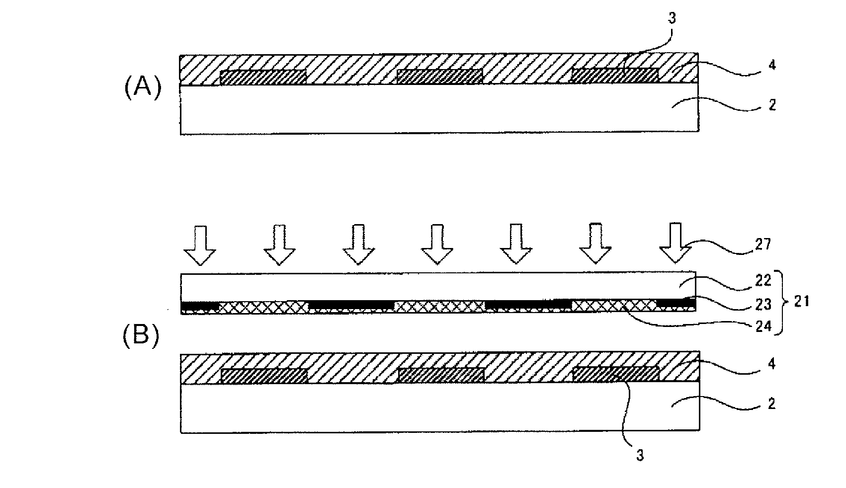
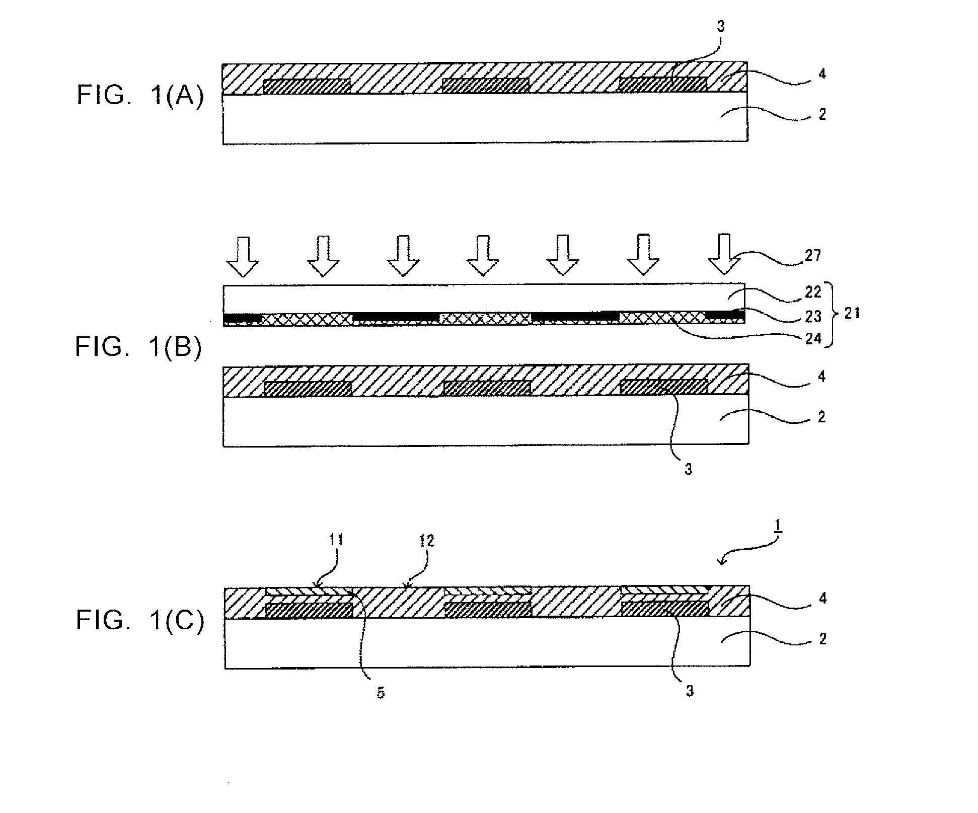
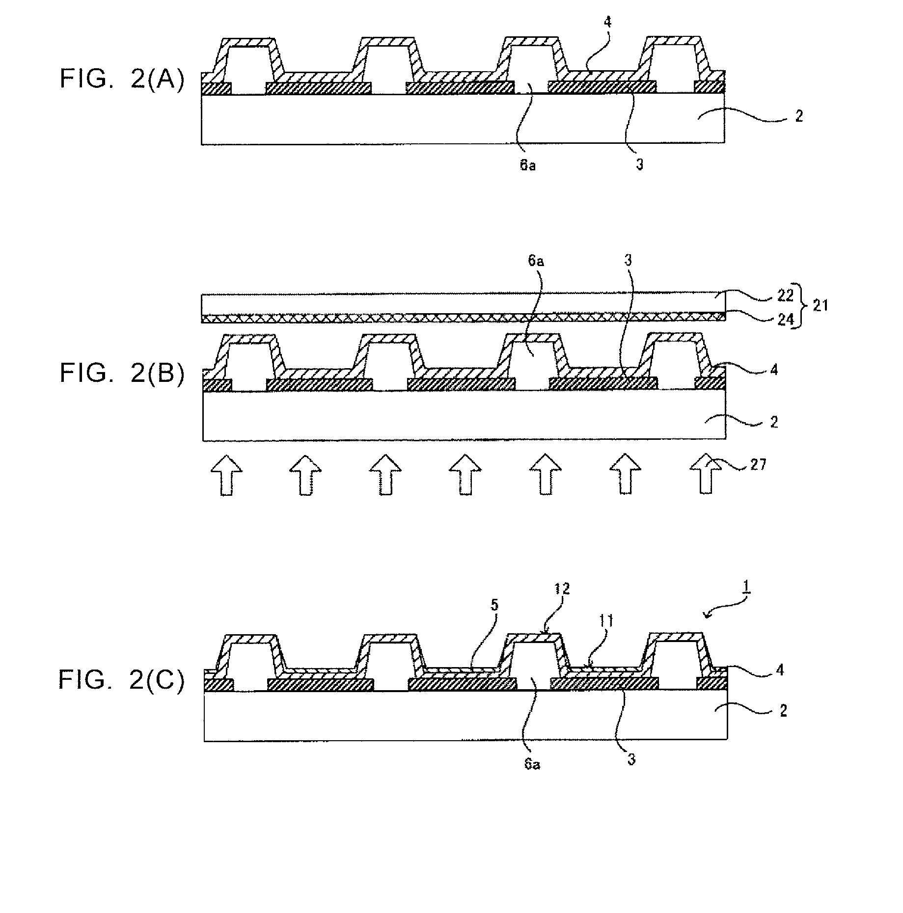
Image

Examples
synthesis example 1
[0317]Molybdenum-containing nanoparticles protected by 4,4,5,5,6,6,7,7,8,8,9,9,10,10,11,11,11-heptadecafluoroundecylamine were synthesized in the following manner. First, 3.2 g of n-octyl ether (manufactured by Tokyo Chemical Industry Co., Ltd.) was weighed out and put into a 25 ml three-necked flask. The pressure inside the flask was reduced while stirring, and the flask was left for 1.5 hours at room temperature (24° C.) for removal of low volatility components. After switching from vacuum to air atmosphere, 0.2 g of molybdenum hexacarbonyl (manufactured by Kanto Chemical Co., Inc.) and 0.4 g of 4,4,5,5,6,6,7,7,8,8,9,9,10,10,11,11,11-heptadecafluoroundecylamine (manufactured by Fluka Chemical Corp.) were added thereto. The mixed solution was heated to 250° C. while stirring in an argon gas atmosphere, and kept at the temperature for one hour. Then, the mixed solution was cooled to room temperature (24° C.). After switching from the argon gas atmosphere to the air atmosphere, 5 g o...
synthesis example 2
[0318]Molybdenum-containing nanoparticles protected by 4-(3,3,4,4,5,5,6,6,7,7,8,8,9,9,10,10,10-heptadecafluorodecyl)benzylamine were synthesized in the following manner. First, 6.4 g of n-octyl ether (manufactured by Tokyo Chemical Industry Co., Ltd.) was weighed out and put into a 25 ml three-necked flask. The pressure inside the flask was reduced while stirring, and the flask was left for 2.5 hours at room temperature (24° C.) for removal of low volatility components. After switching from vacuum to air atmosphere, 0.4 g of molybdenumhexacarbonyl (manufactured by Kanto Chemical Co., Inc.) and 0.9 g of 4-(3,3,4,4,5,5,6,6,7,7,8,8,9,9,10,10,10-heptadecafluorodecyl)benzylamine (manufactured by Sigma-Aldrich Corporation) were added thereto. The mixed solution was heated to 250° C. while stirring in an argon gas atmosphere, and kept at the temperature for one hour. Then, the mixed solution was cooled to room temperature (24° C.). After switching from the argon gas atmosphere to the air a...
synthesis example 3
[0319]Tungsten-containing nanoparticles protected by 4,4,5,5,6,6,7,7,8,8,9,9,10,10,11,11,11-heptadecafluoroundecylamine were synthesized in the following manner. First, 6.4 g of n-octyl ether (manufactured by Tokyo Chemical Industry Co., Ltd.) was weighed out and put into a 25 ml three-necked flask. The pressure inside the flask was reduced while stirring, and the flask was left for 3 hours at room temperature (24° C.) for removal of low volatility components. After switching from vacuum to air atmosphere, 0.4 g of tungstenhexacarbonyl (manufactured by Sigma-Aldrich Corporation) and 0.8 g of 4,4,5,5,6,6,7,7,8,8,9,9,10,10,11,11,11-heptadecafluoroundecylamine (manufactured by Fluka Chemical Corp.) were added thereto. The mixed solution was heated to 250° C. while stirring in an argon gas atmosphere, and kept at the temperature for one hour. Then, the mixed solution was cooled to room temperature (24° C.). After switching from the argon gas atmosphere to the air atmosphere, 10 g of eth...
PUM
| Property | Measurement | Unit |
|---|---|---|
| particle diameter | aaaaa | aaaaa |
| thickness | aaaaa | aaaaa |
| diameter | aaaaa | aaaaa |
Abstract
Description
Claims
Application Information
 - R&D Engineer
- R&D Manager
- IP Professional
- Industry Leading Data Capabilities
- Powerful AI technology
- Patent DNA Extraction
Browse by: Latest US Patents, China's latest patents, Technical Efficacy Thesaurus, Application Domain, Technology Topic, Popular Technical Reports.
© 2024 PatSnap. All rights reserved.Legal|Privacy policy|Modern Slavery Act Transparency Statement|Sitemap|About US| Contact US: help@patsnap.com