
Forming methods

a technology of forming methods and materials, applied in the field of forming methods, can solve the problems of mass production forming or fabricating of nanostructures or microstructures, challenges to existing forming techniques, subsequent deformation of imprinted or formed items or product surfaces, etc., and achieves the effect of shortening the cooling time, shortening the material depth, and speeding up the forming process

Active Publication Date: 2012-04-26
MFG SYST LTD
View PDF6 Cites 11 Cited by
  • Summary
  • Abstract
  • Description
  • Claims
  • Application Information

AI Technical Summary

Benefits of technology

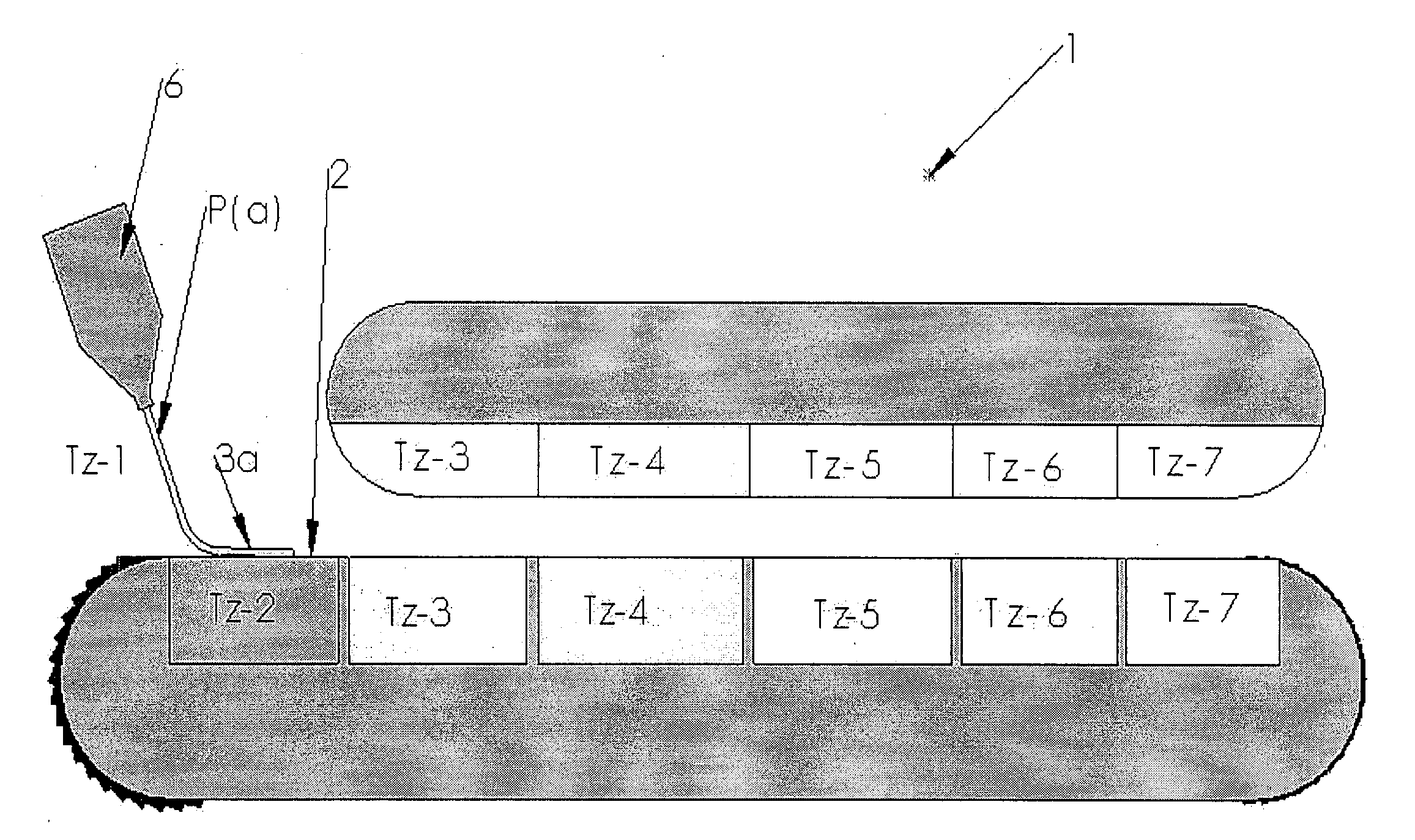
[0072]Preferably, wherein said heater(s) can facilitate the keeping of the polymer above its glass transition temperature at at least the beginning of the forming zone.
[0130]The basic breakdown of materials that may be formed are those that will retain shape or take on a shape or imprint under pressure alone (for example malleable or ductile metals such as lead, copper, zinc or the like, plastics or the like) thermoplastic compounds that require heat to enable them to be formed, thermosetting compounds that require heat or some other form of catalyst in addition with pressure can be formed, or in general thermoformable compounds that require heat and pressure to allow formation thereof. As an example a rubber can be pressure formed but also with the addition of heat may facilitate further cross linking of the rubber molecules so that one the pressure and heat are removed the shape imparted to the rubber material is retained.

Problems solved by technology

Mass production forming or fabricating of nanostructures or microstructures, such as any manufactured structure having a scale between molecular and microscopic, presents challenges to existing forming techniques.
Further disadvantages of forming products have included the subsequent deformation of an imprinted or formed item or product surface by the heat remaining in the material following a forming step.

Method used


Image

  • Forming methods
  • Forming methods
  • Forming methods

Examples


example 1

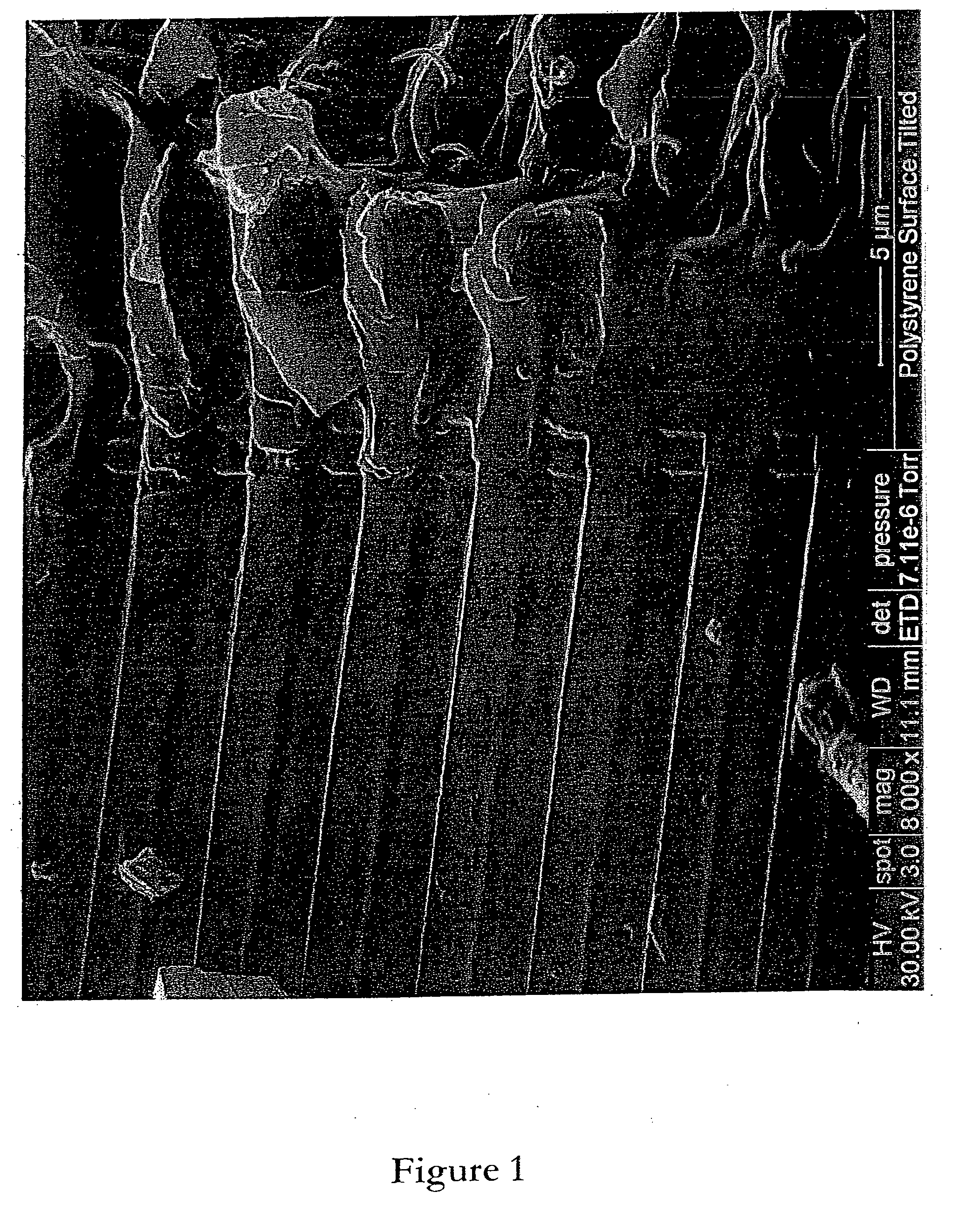
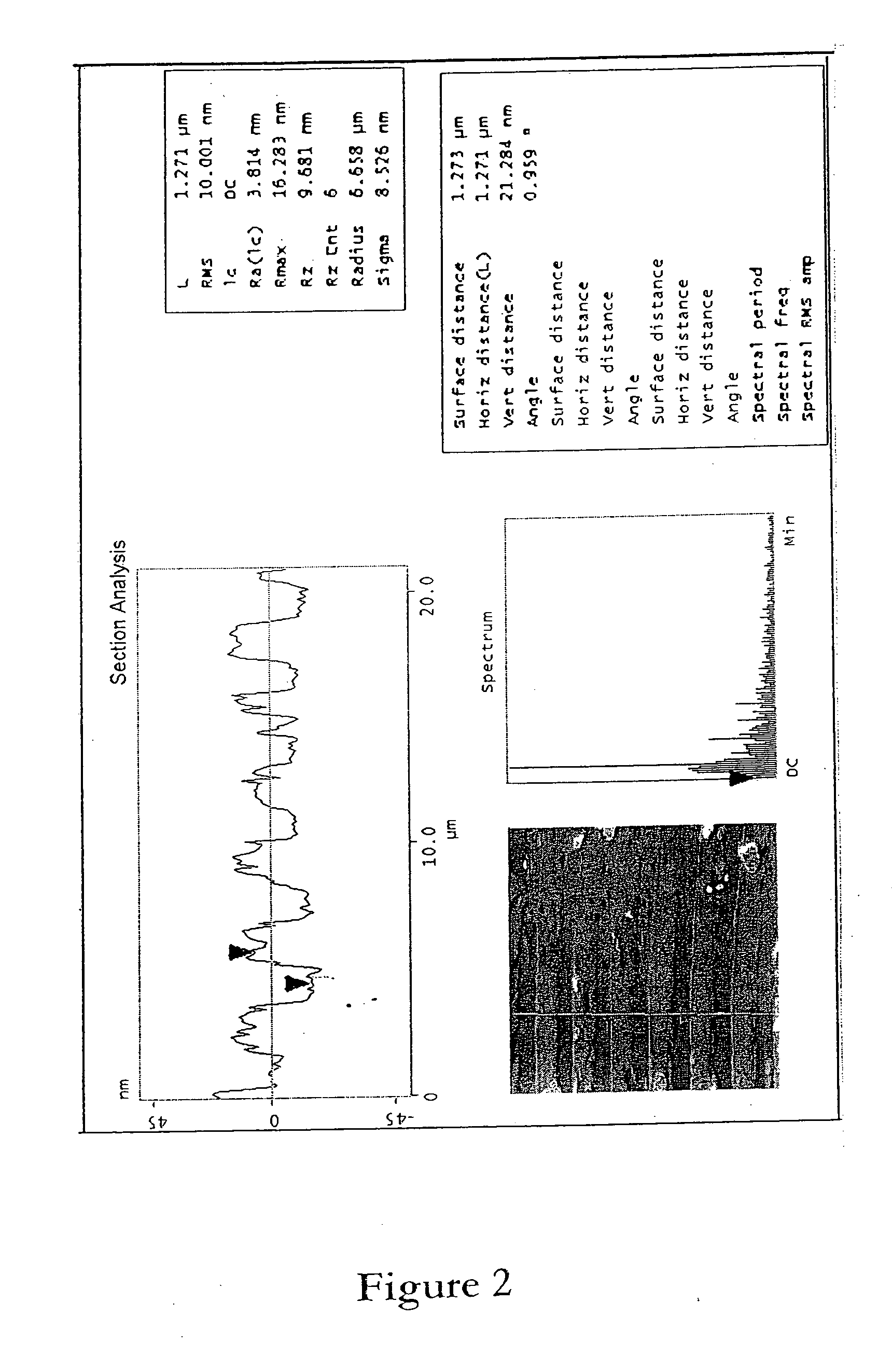
[0272]Polystyrene is:[0273](i) heated and maintained at a temperature of 230° C.,[0274](ii) the heated polystyrene is transferred and applied to a surface of a continuous forming tool, such as the surface labelled 26 or 24 of PCT / NZ2006 / 000300 and formed according to the method of PCT / NZ2006 / 000301,[0275](iii) a pressure of between about 1 kg / cm2 to about 3 kg / cm2 is applied to the material on the surface,[0276](iv) pressure is released by separation of the forming surfaces, thereby releasing the item or product thus formed.

[0277]The product thus formed is that shown in FIG. 1 with product analysis shown in FIG. 2 and an atomic force microscope image of a part of the product shown in FIG. 3.

example 2

[0278]Polycarbonate is:[0279](i) heated and maintained at a temperature of 300° C.,[0280](ii) the heated polycarbonate is transferred and applied to a surface of a continuous forming tool, such as the surface labelled 26 or 24 of PCT / NZ2006 / 000300 and formed according to the method of PCT / NZ2006 / 000301,

[0281](iii) a pressure of between about 1 kg / cm2 to about 3 kg / cm2 is applied to the material on the surface,[0282](iv) pressure is released by separation of the forming surfaces, thereby releasing the item or product thus formed.

[0283]The product thus formed is that shown in FIG. 4 with product analysis shown in FIG. 5.

example 3

[0284]Polymethyl methacrylate (PMMA) is:[0285](i) heated and maintained at a temperature of between 190-240° C.,[0286](ii) the heated PMMA is extruded from an extruder head and flowed in a continuous flow on to the lower moulding surface at a depth or thickness of 1 mm of a moving belt former (MBF) or an endless belt or a continuous forming tool (such as the surface labelled 26 or 24 of PCT / NZ2006 / 000300 and formed according to the method of PCT / NZ2006 / 000301), the PMMA is held on the moulding surface and retained or allowed to remain above its glass transition temperature (Tg PMMA ˜105° C.),[0287](iii) the upper moulding surface is applied to the upper surface of the PMMA held on the lower moulding surface, the upper moulding surface exerting a pressure of between about 1 kg / cm2 to about 3 kg / cm2 to the PMMA material,[0288](iv) pressure is released by separation of the forming (or lower and upper moulding) surfaces, thereby releasing the item or product thus formed.

[0289]The table ...


PUM

PropertyMeasurementUnit
depthaaaaaaaaaa
depthaaaaaaaaaa
depthaaaaaaaaaa

Abstract

This invention relates to methods for forming polymer(s) including heating of a polymer to be formed to a temperature above its glass transition temperature, continuously depositing (preferably by flowing or laying) the polymer onto a moulding surface (herein the “lower moulding surface”) of a first mould, (preferably in a manner that reduces, eliminates or minimises shear stress or other stress in the polymer so deposited), the polymer remaining above the glass transition temperature, applying a moulding surface (herein the “upper surface”) of the polymer while the polymer remains at a temperature above the glass transition temperature, and allowing the polymer to transition to below the glass transition temperature while within or between the upper and lower moulding surfaces, wherein the polymer is removed from the moulding surfaces. Apparatus is also provided.

Description

FIELD OF THE INVENTION[0001]The present invention relates to forming methods, more particularly, though not solely, to a method of forming or fabricating superfine structures or nanostructures or both.BACKGROUND TO THE INVENTION[0002]Mass production forming or fabricating of nanostructures or microstructures, such as any manufactured structure having a scale between molecular and microscopic, presents challenges to existing forming techniques.[0003]For example, an item or a precursor to an item manufactured in a forming process, such as by injection moulding, may have been formed in a stressed material state. The forming process itself imparts stresses such as deformation stress, shear stress, flow stress and temperature stress to the material or item thus formed. Generally, in existing forming techniques the greater the speed of production the more stress tends to be imparted in to the formed product. Traditionally, these stresses are increased greatly when attempting to mass produ...

Claims


Application Information

Patent Timeline
Patent Type & Authority Applications(United States)
IPC IPC(8): B32B3/00B29C43/34B29C43/52B29C69/02B29C43/00B29C43/22B29C48/05B29C48/305B82Y40/00
CPCB29C43/222B29C43/305B29C47/0019B29C47/0021B29C47/0033B29C47/0038Y10T428/24355B29C47/0054B29C47/065B29C47/145B29C47/885B29C2043/025B29K2995/0072B29C47/0047B29L2031/756B29C43/48B29C59/04B29C2043/483B29C2059/023B29C48/914B29C48/001B29C48/07B29C48/08B29C48/918B29C48/9145B29C48/13B29C48/0014B29C48/0017B29C48/21B29C48/307B29C43/52B29C2043/522B29C48/05B30B5/04B29C48/30B29C39/06B29C39/38B82B3/00B29C43/24B29C43/58B29C2043/5816B29C2043/5875
Inventor HAYNES, ANDREW LEONICHOLLS, CHRISTOPHER JOHN
Owner MFG SYST LTD
Learn More