
Dielectric material with non-linear dielectric constant

Inactive Publication Date: 2011-06-16
3M INNOVATIVE PROPERTIES CO
View PDF15 Cites 24 Cited by
  • Summary
  • Abstract
  • Description
  • Claims
  • Application Information

AI Technical Summary

Benefits of technology

[0011]“electrical contact” between a conductive material and an inorganic particle means that a portion of the conductive material is touching, or is in sufficient physical proximity to, the inorganic particle so that a charge can travel between

Problems solved by technology

These high loadings drastically reduce the processability and mechanical properties of the resulting composites.
For many polymer matrixes, loadings at these levels are not very practical.
For carbon filled composites, the volume loading of carbon powder should be near the percolation threshold which is very hard to control.
These types of composites generally have high dielectric losses (dissipation factor).
As a result, such a composite can lead to an increase in temperature in the dielectric material, which can exceed the thermal load capability of the connector and cable.

Method used


Image

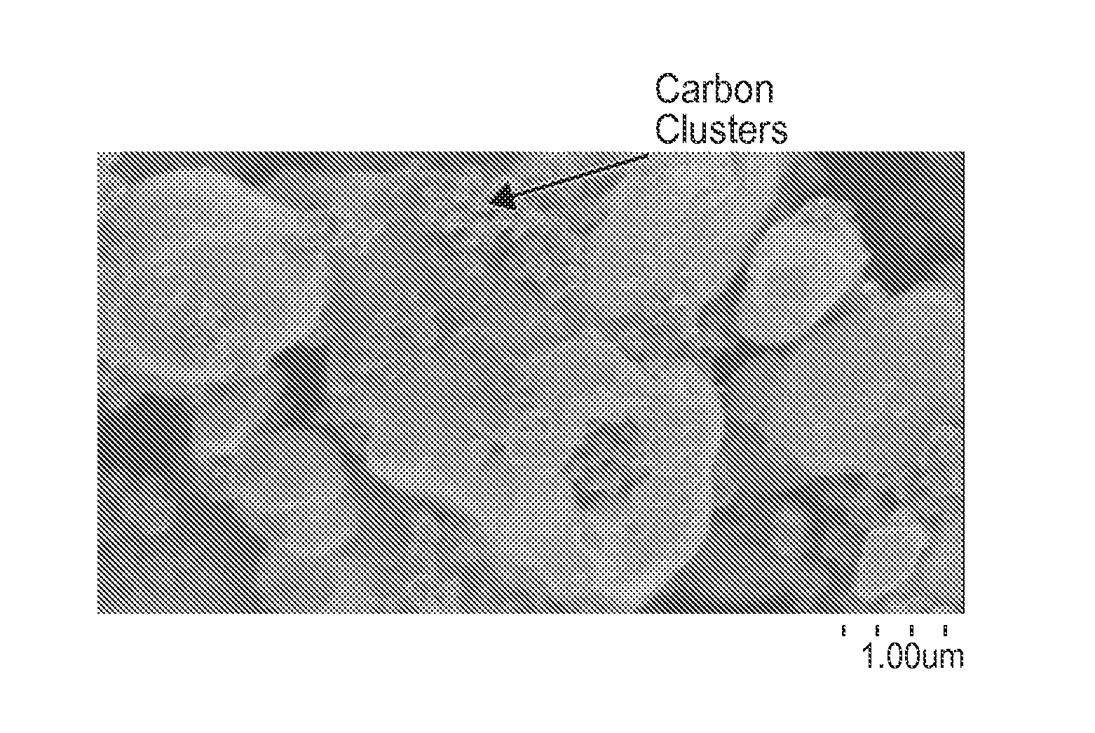
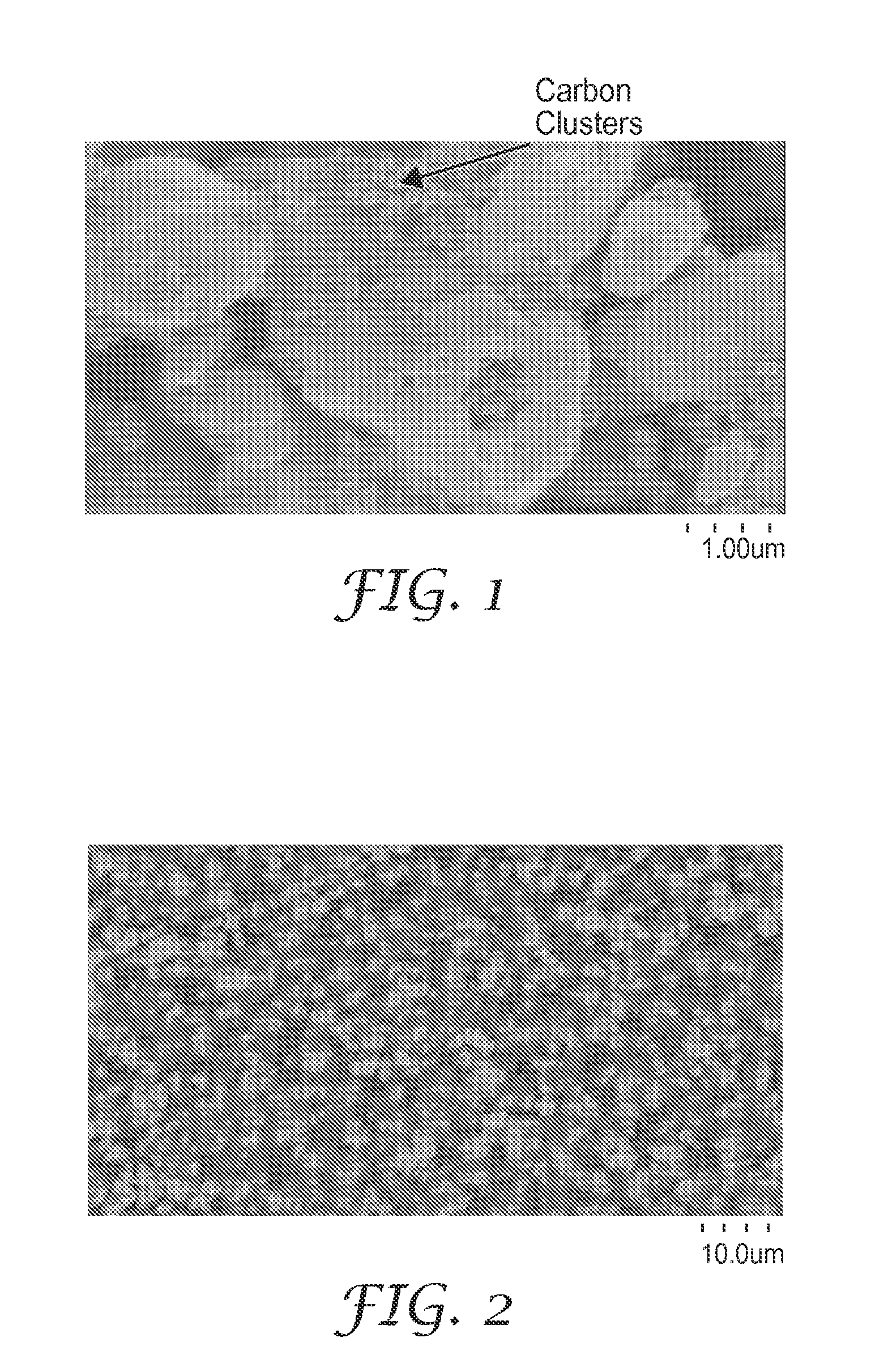
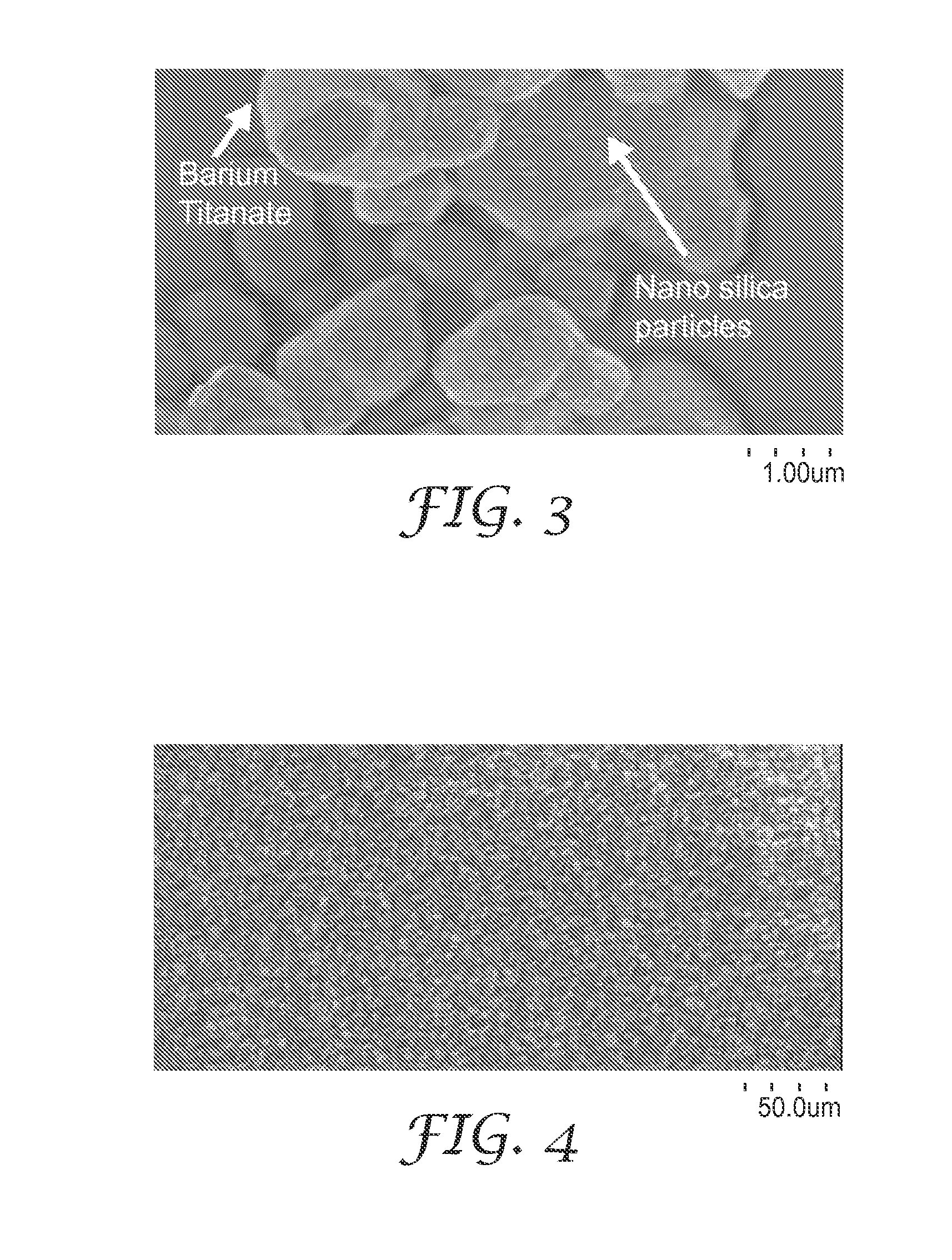
  • Dielectric material with non-linear dielectric constant
  • Dielectric material with non-linear dielectric constant
  • Dielectric material with non-linear dielectric constant

Examples


examples 6-8

Fillers with Different K Values

[0066]In these examples, barium titanate particles were substituted with silica, titanium dioxide calcium titanate, and strontium titanate particles. Silicone rubber disks were prepared as described for Examples 1-5 after grinding 30 volume percent of each type of inorganic particle with 3 volume percent of carbon powder. Electrical properties of each of these disks were then measured. The test results are summarized in Table 3, along with the test results for Example 3. In addition, non-linear dielectric properties were measured for Examples 6-8. The test results are shown in FIG. 8.

TABLE 3InorganicDielectricparticleCompositeDissi-BreakdownInorganicdielectricDielectricpationstrengthEx.particleconstantConstantfactor (D)(V / mil)6Silica38.90.0322687Titanium dioxide70-8011.90.0052058Calcium Titanate200-30018.40.0142173Barium Titanate2000-400021.70.0139180.4

example 9

[0067]In this example, carbon powder was substituted with 18 volume percent aluminum powder (10 micron size) (calculated using a density of 1.5 g / cc). A silicone rubber disk was prepared as described in Examples 1-5 after grinding the Al powder with 24.5 volume percent barium titanate. The resultant disk had a dielectric constant (K) of 20.8 and a dissipation factor of 0.022.

example 10

Preparation of Hydrophobically Modified Nanosilica Particle

[0068]A mixture of 100 grams of colloidal silica (16.06 wt. % solids in water; 5 nm size), 7.54 grams of isoctyltrimethoxy silane, 0.81 grams of methyltrimethoxysilane and 112.5 grams of an 80:20 wt / wt. % solvent blend of ethanol:methanol were added to a 500 ml 3-neck round bottom flask (Ace Glass, Vineland, N.J.). The flask containing the mixture was placed in an oil bath set at 80° C. with stirring for 4 hours to prepare hydrophobically modified nanosilica particles. The hydrophobically modified nanosilica particles were transferred to a crystallizing dish and dried in a convection oven at 150° C. for 2 hours.

Nanosilica Particle Modification of Barium Titanate Filler:

[0069]Barium titanate particles (particle size 0.8-2.1 microns) were modified by mixing (using a spatula) with the hydrophobically modified nanosilica particles (0.75 wt %) and dispersing in excess toluene. The barium titanate and nanosilica particle mixture w...


PUM


Abstract

Provided is a composition comprising a polymeric material, a filler material dispersed in the polymeric material, the filler material comprising inorganic particles and a discontinuous arrangement of conductive material wherein at least a portion of the conductive material is in durable electrical contact with the inorganic particles, and conductive material dispersed in the polymeric material.

Description

CROSS REFERENCE TO RELATED APPLICATION[0001]This application claims the benefit of U.S. Provisional Patent Application No. 61 / 286,247, filed Dec. 14, 2009, the disclosure of which is incorporated by reference herein in its entirety.TECHNICAL FIELD[0002]This invention relates to a dielectric material having a non-linear dielectric constant and other properties useful for electrical stress relief.BACKGROUND[0003]High dielectric constant (Hi-K) elastomeric composites are commonly used in cable accessories to control electrical field stresses built up at the locations of splices and terminations. Typically, these materials are carbon black filled elastomers such as EPDM and silicone that give a certain range of dielectric (K) values for stress relief. These elastomeric composites also contain barium titanate (BT) or inorganic fillers that have very high dielectric constants (Hi-K). In order to achieve high dielectric constant of these composites, high filler loadings (>50 volume perc...

Claims


Application Information

Patent Timeline
IPC IPC(8): H01B1/24H01B1/20H01B1/22B82Y30/00
CPCH01B3/004H02G15/184H02G15/103H02G15/064H01B1/24H01B1/22H01B3/28
Inventor SOMASIRI, NANAYAKKARA L.D.BARAN, JR., JIMMIE R.LOTTES, ANDREW C.JIANG, GEVEERARAGHAVAN, BADRIHUYNH, PAUL V.GHOSH, DIPANKAR
Owner 3M INNOVATIVE PROPERTIES CO
Learn More