
Method of using syngas cooling to heat drying gas for a dry feed system

a technology of heat drying gas and dry feed system, which is applied in the field of dry feed system heat drying gas using syngas cooling, can solve the problems of reducing overall plant efficiency, not being able to economically dry solid feedstock, and not being able to provide the necessary heat engine for separate power plant facilities,

Inactive Publication Date: 2010-12-16
GENERAL ELECTRIC CO
View PDF30 Cites 21 Cited by
  • Summary
  • Abstract
  • Description
  • Claims
  • Application Information

AI Technical Summary

Benefits of technology

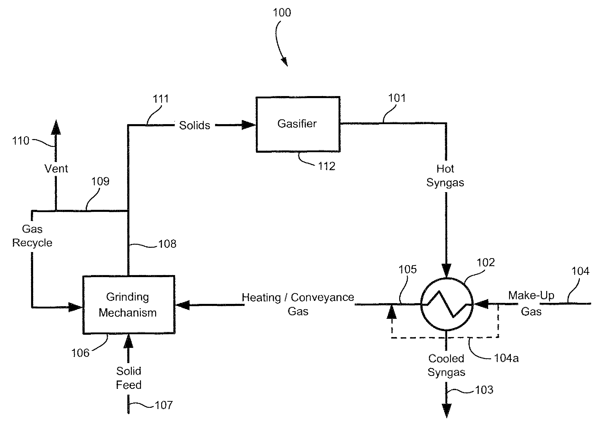
[0005]The present invention comprises a method for improving the overall thermal efficiency of a coal power generation plant by transferring heat from a synthesis gas stream to solid fuel used as the primary feed to the gasifier. An exemplary embodiment includes the steps of initially cooling the raw syngas exhaust by transferring heat to a makeup gas feed to the feed preparation equipment, simultaneously feeding a solid fuel component (e.g., sub-bituminous coal) along with a portion of a conveyance / drying gas stream (e.g., inert gas) into a grinding mechanism (e.g., grinding mill) for the solid feedstock, forming a two-phase solids / gas stream comprising ground feedstock particulates and conveyance / drying gas, simultaneously heating and drying the ground solid feedstock particulates to remove water and increase the feedstock temperature, separating and removing substantially all of the water vapor formed in the heating and drying step, and feeding the heated and dried solids stream to the gasifier. The invention also contemplates a new syngas cooler design for transferring heat to the makeup gas stream used in the process and a related system using the various new syngas cooler designs.

Problems solved by technology

In the case of coal used as the feedstock, most gasification processes require relatively dry (low moisture content) coal because of the difficulties in conveying moist solids and the inherent efficiency losses associated with moisture present in the coal feedstock.
However, the known sources of heating and drying solids feedstocks have drawbacks that invariably reduce overall plant efficiency.
The direct firing of those fuels creates a pollutant emissions source and thus they often are not an acceptable method to economically dry a solids feedstock.
Again, the need for separate power plant facilities to provide the necessary heat engine often is not an economical alternative.
Milling and drying plants can reduce the overall efficiency of the power generating plant because they consume part of the gaseous fuel.
However, the net efficiency of the power generating plant necessarily decreases.
In addition, emissions such as sulfur from the power plant increase when making drying energy available in that manner.

Method used


Image

  • Method of using syngas cooling to heat drying gas for a dry feed system
  • Method of using syngas cooling to heat drying gas for a dry feed system
  • Method of using syngas cooling to heat drying gas for a dry feed system

Examples


second embodiment

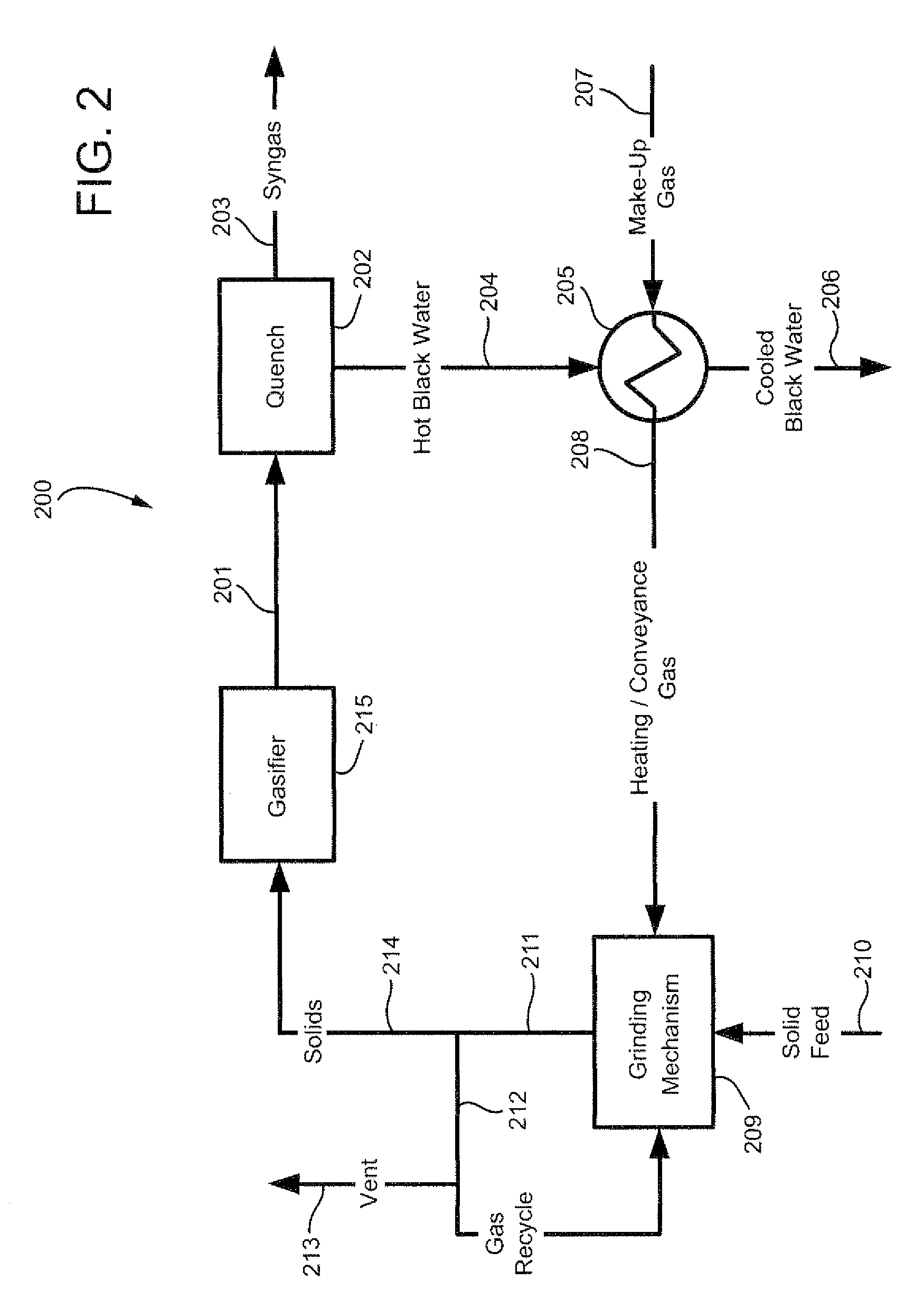
[0031]Referring now to FIG. 2, an exemplary process flow diagram of the process according to the invention is depicted generally at 200, again using the heat removed from the hot syngas as the principal means to dry a solids feedstock. However, in this embodiment, the hot syngas produced by gasifier 215 (nominally at about 2500° F.) in exit stream 201 initially passes through a quench cycle 202 such as a gas-to-liquid heat exchanger which initially cools the syngas as shown leaving the quench cycle at 203.

first embodiment

[0032]The resulting hot liquid stream from the quench cycle at approximately 450° F. (labeled “hot black water”) 204 serves as the primary heating medium for recovering the residual syngas exhaust heat using syngas cooler 205. The cooled black water stream 206 typically is on the shell side of syngas cooler 205. The tube side includes makeup gas stream 207 consisting primarily of oxygen limited gas as described above which picks up a substantial amount of heat on the tube side to form hot “heating / conveyance” gas 208 for use in the grinding mill as generally described above in connection with the

[0033]As FIG. 2 also illustrates, the solids coal feed 210 to the grinding mill 209 loses a substantial fraction of entrained liquid (e.g., water vapor) during the grinding step after exiting grinding mill as shown at 211. This particular embodiment thus contemplates using a recycle stream 212 and vent arrangement as shown for the purpose of removing excess water vapor via vent line 213 as d...

third embodiment

[0036]Also similar to earlier embodiments, the heat recovery system depicted in the third embodiment recycles a certain amount of the entrained solids / vapor stream to the grinding mechanism (see recycle 314), for example by passing the two phase recycle through a cyclone separator to drop out the entrained particulates and venting a portion of the vapor stream as shown at 315 containing water vapor and fines generated during the prior heating and pulverizing steps. The considerably drier, vapor and particulate feedstock solids stream 316 is then fed to gasifier 317.


PUM


Abstract

A method for improving the overall thermal efficiency of a coal power generation plant by transferring heat from a raw synthesis gas stream to solid fuel used as the primary feed to the gasifier, comprising the steps of initially cooling the syngas exhaust by transferring heat to a makeup conveyance gas feed to the dry feed preparation system, feeding a solid fuel component and a portion of the makeup gas stream into a grinding mechanism for the solid feedstock, forming a two-phase solids / gas stream comprising ground feedstock particulates and makeup gas, heating and drying the ground solid feedstock particulates to remove water, separating and removing water vapor formed in the heating and drying step, and feeding the heated and dried solids / gas stream to the gasifier.

Description

BACKGROUND OF THE INVENTION[0001]The present invention relates to a method for improving the overall efficiency of coal power generation plants by transferring heat from a synthesis gas stream to solid fuel used as the primary feed to the combustors of a gas turbine engine.[0002]The gasification of solid feedstocks and subsequent combustion of hydrocarbon components from the feedstock in a gas turbine engine are known. In the case of coal used as the feedstock, most gasification processes require relatively dry (low moisture content) coal because of the difficulties in conveying moist solids and the inherent efficiency losses associated with moisture present in the coal feedstock. Since almost all commercially available coals contain a certain amount of water, the need exists to dry the coal in an efficient manner prior to gasification. That need becomes even more important when using sub-bituminous, lignite or brown coal feedstocks that often contain between about 20% and about 65%...

Claims


Application Information

Patent Timeline
Patent Type & Authority Applications(United States)
IPC IPC(8): F26B3/02F26B21/14F26B23/02B02C23/18F28D3/00
CPCF23K1/04F26B21/14F26B23/001C10J3/506C10J3/74C10J3/76C10J3/84C10K1/026C10K1/101C10J2300/0906C10J2300/0909C10J2300/093C10J2300/1884Y02P70/405Y02E20/18Y02P70/10
Inventor RUSSELL, STEVEN CRAIGCORRY, JUDETH BRANNONFREY, GEROGE FREDERICKMISHRA, SUNIL RAMABHILAKHMALL, OMPRAKASH
Owner GENERAL ELECTRIC CO
Learn More