
Conductive compositions containing blended alloy fillers

a technology of alloy fillers and conductive compositions, applied in the field of metal compositions, can solve the problems of entrapment of plating solution, a significant issue, and a potential source of defects, and achieve the effect of facilitating the formation of desired end products

Active Publication Date: 2010-10-07
ORMET CIRCUITS
View PDF33 Cites 54 Cited by
  • Summary
  • Abstract
  • Description
  • Claims
  • Application Information

AI Technical Summary

Benefits of technology

The present invention relates to metallurgical compositions that can be processed at temperatures below 300°C and have high tolerance to thermo-mechanical stress. The compositions have high specificity of metallurgical component selection and can form intermetallics with other metals. The metallic components in the compositions undergo reactions that can be thought of as analogous to organic chemistry reactions. The invention also provides methods for introducing metallic reagents and organic compounds that can enhance the reaction. The metallic compositions can be used to form intermetallics with low melting point metals, such as tin, and high melting point metals, such as copper or silver. The invention also provides methods for introducing intermetallics with specific compositions and structures.

Problems solved by technology

It is cost prohibitive to plate solid metal vias to form such layer-to-layer interconnections and entrapment of plating solution is a significant issue.
The dimple created in the center of the via is also a potential source of defects.
One solution is to fill the via hole with a conductive compound, but prior art via fill materials do not form electrically robust interfaces with the copper pads.
The elimination of lead in particular has complicated the manufacture of electronic devices as this element has been used extensively in the past.
But these high tin alloys have melting temperatures roughly 30° C. higher than the prior tin-lead alloys, resulting in commensurate increases in component assembly process temperatures.
Elimination of lead as a viable constituent metal presented a significant challenge to realizing the potential of the technology.

Method used

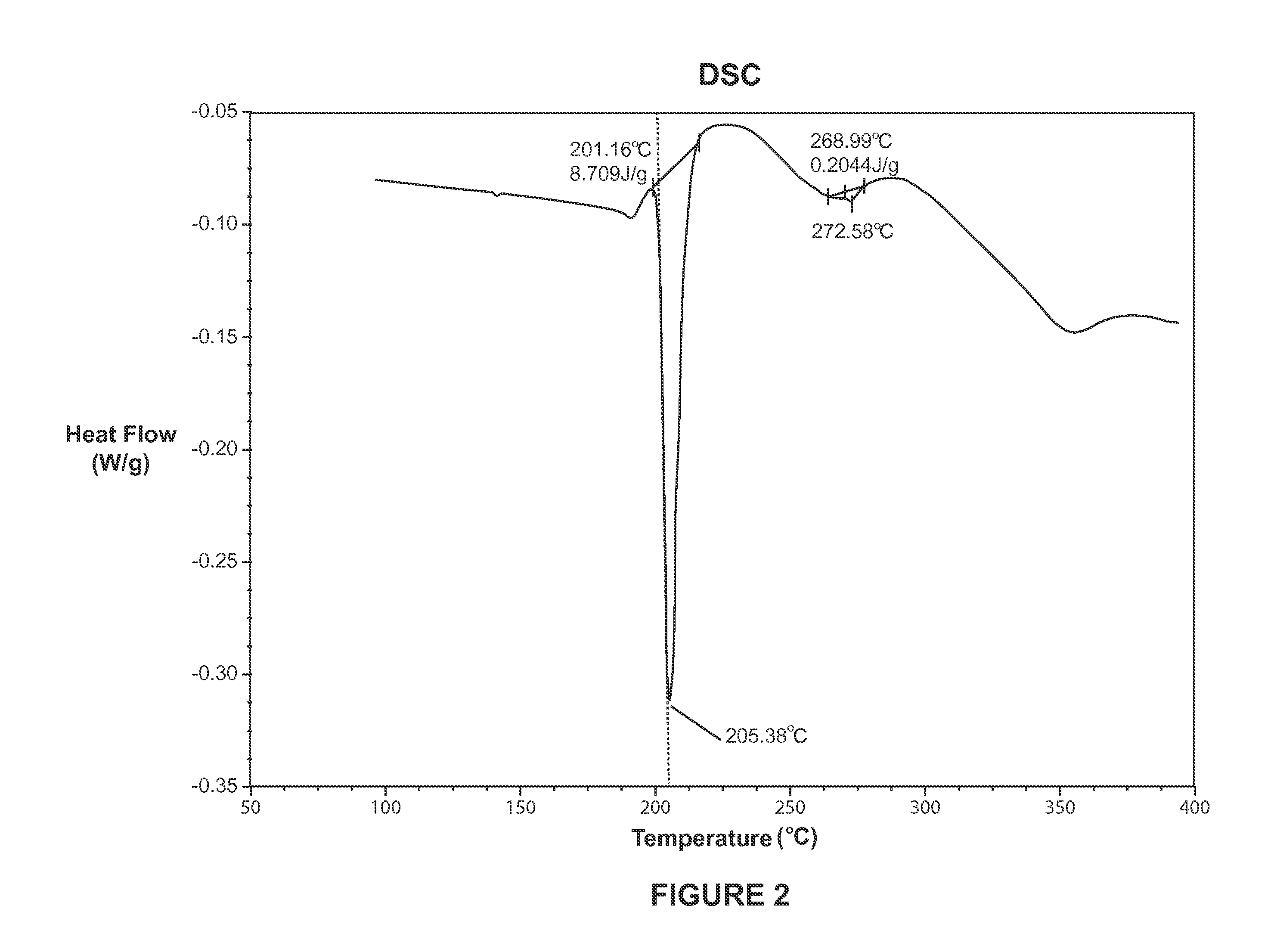
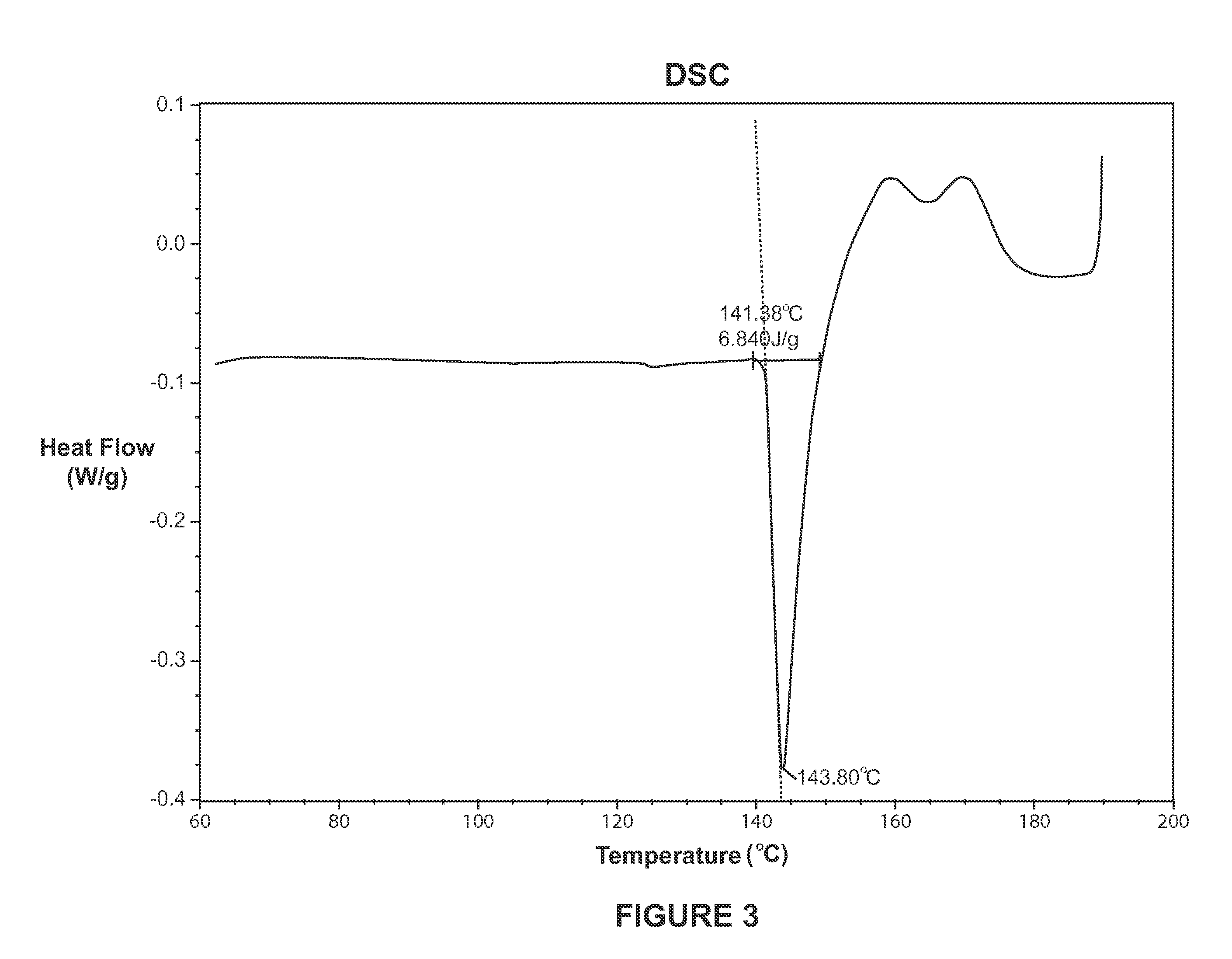

Image

  • Conductive compositions containing blended alloy fillers
  • Conductive compositions containing blended alloy fillers
  • Conductive compositions containing blended alloy fillers

Examples


example 1

[0094]To exemplify the above-described features of the invention, two or more different, but compatible, alloys were combined by mixing to form a non-standard or “blended” alloy in situ. All of the alloy powder constituents need not be molten at the desired process temperature provided that at least one of the metallic alloy powders becomes molten and that the non-molten alloy constituents are highly soluble in the molten constituent. For example, one way of mitigating the potentially deleterious characteristics of Bi in a conductive compositions is by employing an alloy of Sn and Bi in which the proportion of Bi is substantially reduced. Such an alloy is not commonly available; however, alloy powders of eutectic Sn—Bi as well as alloys predominantly comprising Sn are readily available.

[0095]Three compositions A, B and C were prepared summarized below in Table 1.

TABLE 1Compositions A, B and CComponentComposition AComposition BComposition C58 / 42 (mass %) Bi / Sn38.129.91alloy, g40 / 60 (...

example 2

[0100]Two or more different, but compatible alloys were combined. The composition was prepared by mixing the following ingredients: about 4.0 g of Bi / Sn alloy containing about 58 mass % of Bi and about 42 mass % of Sn; about 8.5 g of SAC 305 described in Example 1; about 4.0 g of the eutectic In / Sn alloy containing about 58 mass % of In and about 42 mass % of Sn; about 30.0 g of Cu; and about 5.0 g of the organic vehicle.

[0101]The above described composition contained about 65 mass % of Cu, about 25 mass % of Sn and about 5 mass % of Bi (as percentages of the total metal contents in the composition).

[0102]The process temperature was about 190° C., at which temperature the first and third alloys described above melted, homogenized with the second alloy and reacted with Cu, such that several intermetallic and / or alloy species were created simultaneously. As can be seen, the eutectic In / Sn alloy, which is the least expensive and most readily available of the indium alloys, was blended ...

examples 3-10

[0104]Various compositions were prepared by mixing the indicated compounds in the quantities shown in the following Table 3.

TABLE 3Compositions of Examples 3-10Example No.Component3456789101 mμ Cu (spherical)3.113.064.526.172.952.502.602.223 mμ Cu (spherical)16.1415.8916.0514.4015.4813.1413.5111.665-15 mμ 60 / 40 (mass %)14.3814.3815.6417.04Sn / Bi (non-eutectic)sub 625 mesh 42 / 5814.9714.9516.7617.87(mass %) SnBi (eutectic)sub 625 mesh 99.3 / 0.0715.7214.9514.9515.8317.2217.0418.15(mass %) Sn / Cusub 625 mesh SAC 30516.06Organic Vehicle (as above)6.046.046.046.046.046.046.046.04Total55.9855.9955.9455.9455.9455.9455.9455.94

[0105]The compositions shown in Table 3 contained the quantities of specific metals shown in Table 4.

TABLE 4Quantities of Metals in Compositions of Examples 3-10Example No.Component345678910Total Composition, g55.9855.9955.9455.9455.9455.9455.9455.94Total Cu, g19.2518.9420.5720.5719.8016.8017.3014.90Total alloy, g30.6931.0029.3329.3333.8036.8036.3038.70Cu, mass % of total ...


PUM

PropertyMeasurementUnit
melting temperatureaaaaaaaaaa

Abstract

The present invention provides electrically and thermally conductive compositions for forming interconnections between electronic elements. Invention compositions comprise three or more metal or metal alloy particle types and an organic vehicle comprising a flux that is application specific. The first particle type includes a reactive high melting point metal that reacts with a reactive low melting point metal(s) in the other particles to form intermetallic species. The reactive low melting point metal(s) of the invention are provided in two distinct particle forms. The first reactive low melting point metal particle includes a carrier that facilitates the reaction with the reactive high melting point metal. The second reactive low melting point metal particle acts primarily as a source of the reactive low melting point metal. Combination of the three particle types provides several advantages including reduction of the undesirable characteristics of the carrier metal while preserving and, in some embodiments, enhancing, the advantageous facilitation of the metallic reaction.

Description

CROSS REFERENCE TO RELATED APPLICATIONS[0001]This application claims the benefit of priority under 35 USC §119 of U.S. Provisional Application Ser. No. 61 / 166,015 filed Apr. 2, 2009, the entire disclosure of which is incorporated herein by reference.FIELD OF THE INVENTION[0002]The present invention relates to metal compositions, methods of preparation and uses therefor. More specifically, the present invention relates to conductive metal compositions utilizing blended alloy fillers.BACKGROUND OF THE INVENTION[0003]Over the last few decades, the electronics industry has continually driven towards higher performance and functionality in smaller form factors. At the production level, these driving forces have translated into smaller circuit features, designs and manufacturing methods that support more efficient circuit routing, elimination of layers of packaging, and sophisticated engineered materials. Issues that have been exacerbated by these trends include thermal management and man...

Claims


Application Information

Patent Timeline
Patent Type & Authority Applications(United States)
IPC IPC(8): B23K31/02B22F1/00B32B15/02B22F1/10
CPCB22F1/0003B22F1/0059H05K2201/0272H05K3/321H05K2201/0221B22F7/064B22F1/10B22F1/09H01B1/026H01B1/16H01B1/22
Inventor SHEARER, CATHERINEHOLCOMB, KENNETH C.FRIESEN, G. DELBERTMATTHEWS, MICHAEL C.
Owner ORMET CIRCUITS
Learn More