
High temperature additive manufacturing systems for making near net shape airfoils leading edge protection, and tooling systems therewith

a technology of additive manufacturing and leading edge protection, which is applied in the direction of electron beam welding apparatus, non-electric welding apparatus, chemical vapor deposition coating, etc., can solve the problems of high tooling cost, environmental protection, high yield loss, and affecting the physical and mechanical properties of components, so as to reduce the contamination of the metallic deposit

Inactive Publication Date: 2010-09-30
GENERAL ELECTRIC CO
View PDF16 Cites 75 Cited by
  • Summary
  • Abstract
  • Description
  • Claims
  • Application Information

AI Technical Summary

Benefits of technology

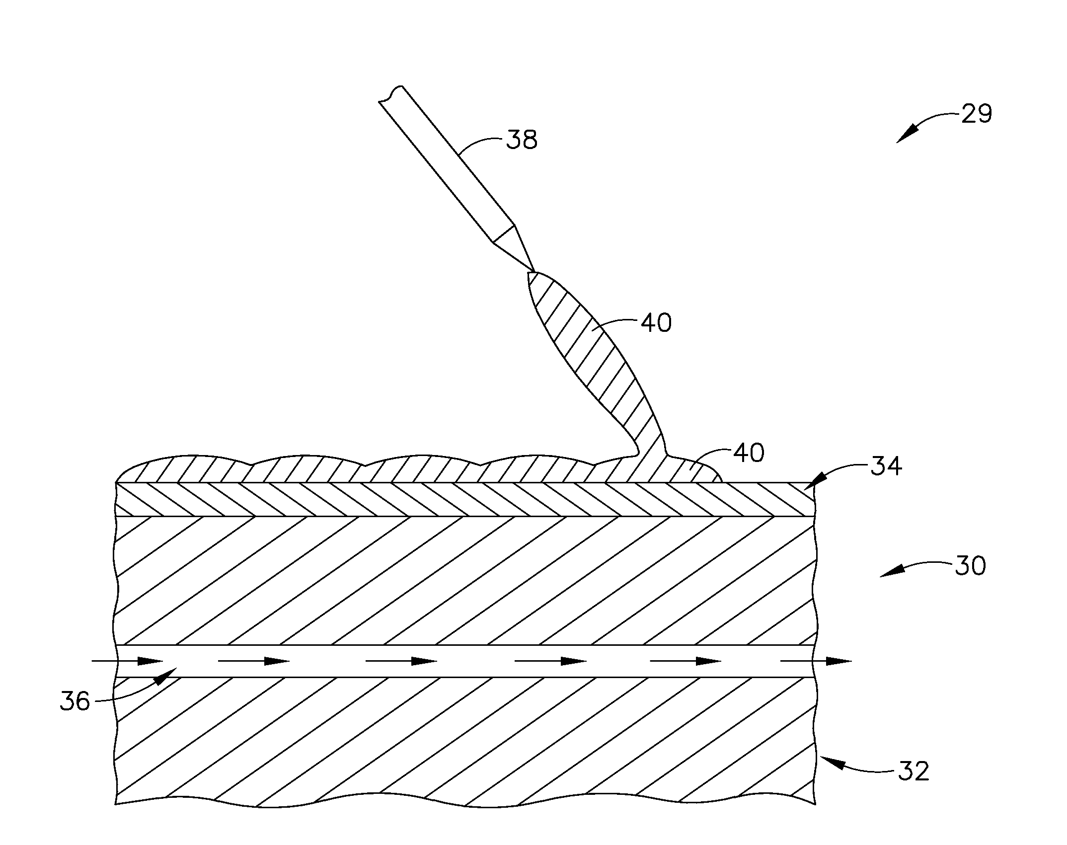
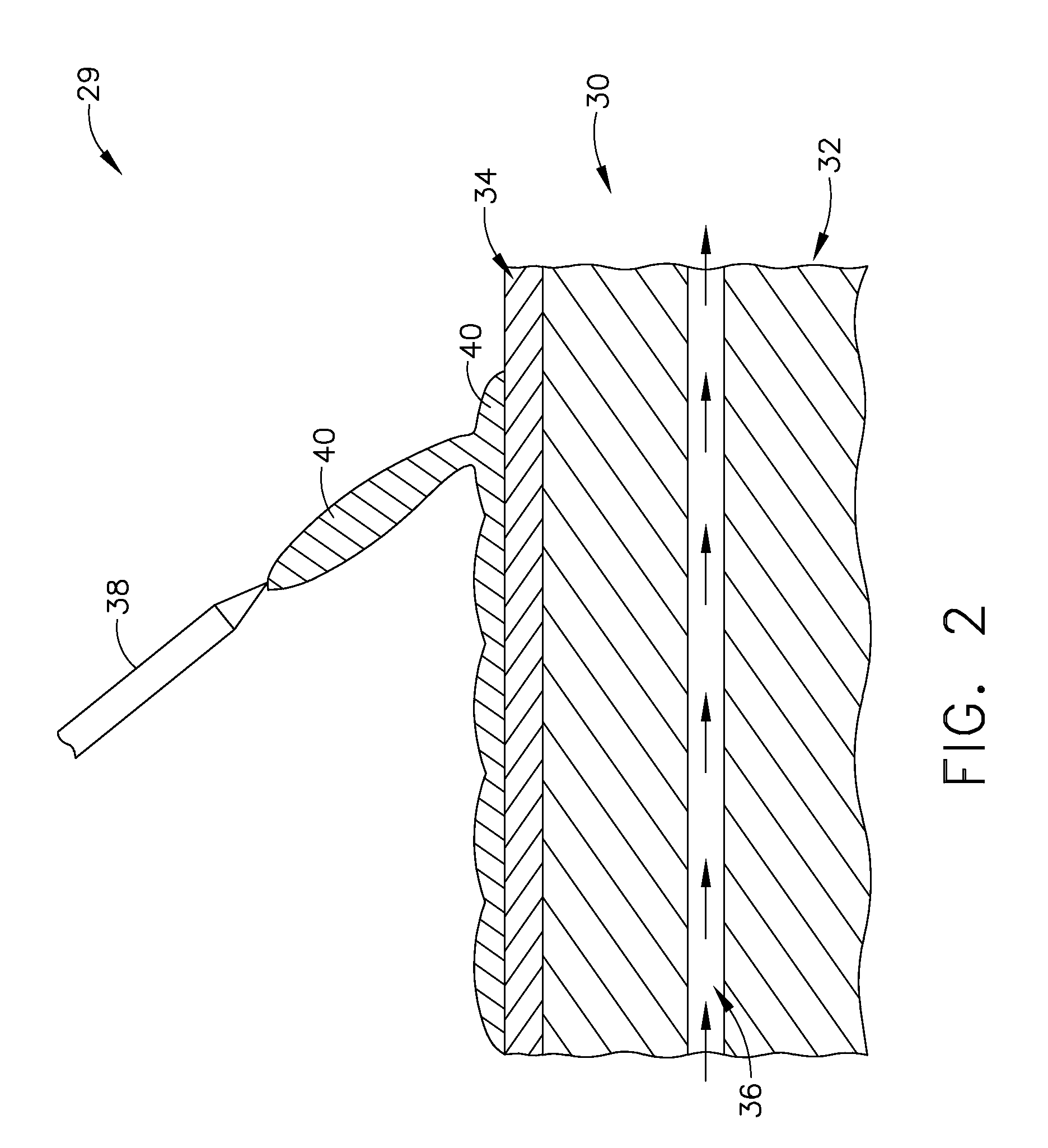
[0008]Embodiments herein generally relate to tooling systems comprising a mandrel for receiving, and providing shape to, a metallic deposit applied using a high temperature additive manufacturing device; a metallic cladding applied to the mandrel for reducing contamination of the metallic deposit; and at least one cooling channel associated with the mandrel for removing heat from the system.
[0009]Embodiments herein also generally relate to high temperature additive manufacturing systems comprising a high temperature additive manufacturing device for providing a metallic deposit; and a tooling system comprising: a mandrel for receiving, and providing shape to, the metallic deposit; a metallic cladding applied to the mandrel for reducing contamination of the metallic deposit; and at least one cooling channel associated with the mandrel for removing heat from the system.

Problems solved by technology

This can lead to high tooling costs, high yield losses, and environmentally unfriendly processing.
These drawbacks are especially true when fabricating thin, complex geometries, such as MLE protective strips.
Additionally, the tool must not cause any contamination of the metallic deposit, as contamination can have a disastrous affect on the physical and mechanical properties of the component.
More specifically, when titanium or titanium alloy is deposited, the risk of contamination of the deposit by the tooling is high due to the high melting point and reactive nature of titanium.
While this approach helps mitigate the issue of contamination, it results in a very narrow process window for making a sound deposit without fusion of the deposit to the tool.
This is because titanium is a relatively poor heat conductor when compared to other heat sink materials (e.g. refractory metals, mild steel, copper).

Method used


Image

  • High temperature additive manufacturing systems for making near net shape airfoils leading edge protection, and tooling systems therewith
  • High temperature additive manufacturing systems for making near net shape airfoils leading edge protection, and tooling systems therewith
  • High temperature additive manufacturing systems for making near net shape airfoils leading edge protection, and tooling systems therewith

Examples


Embodiment Construction

[0014]Embodiments described herein generally relate to high temperature additive manufacturing systems for making near net shape airfoil leading edge protective strips and tooling systems for use therewith.

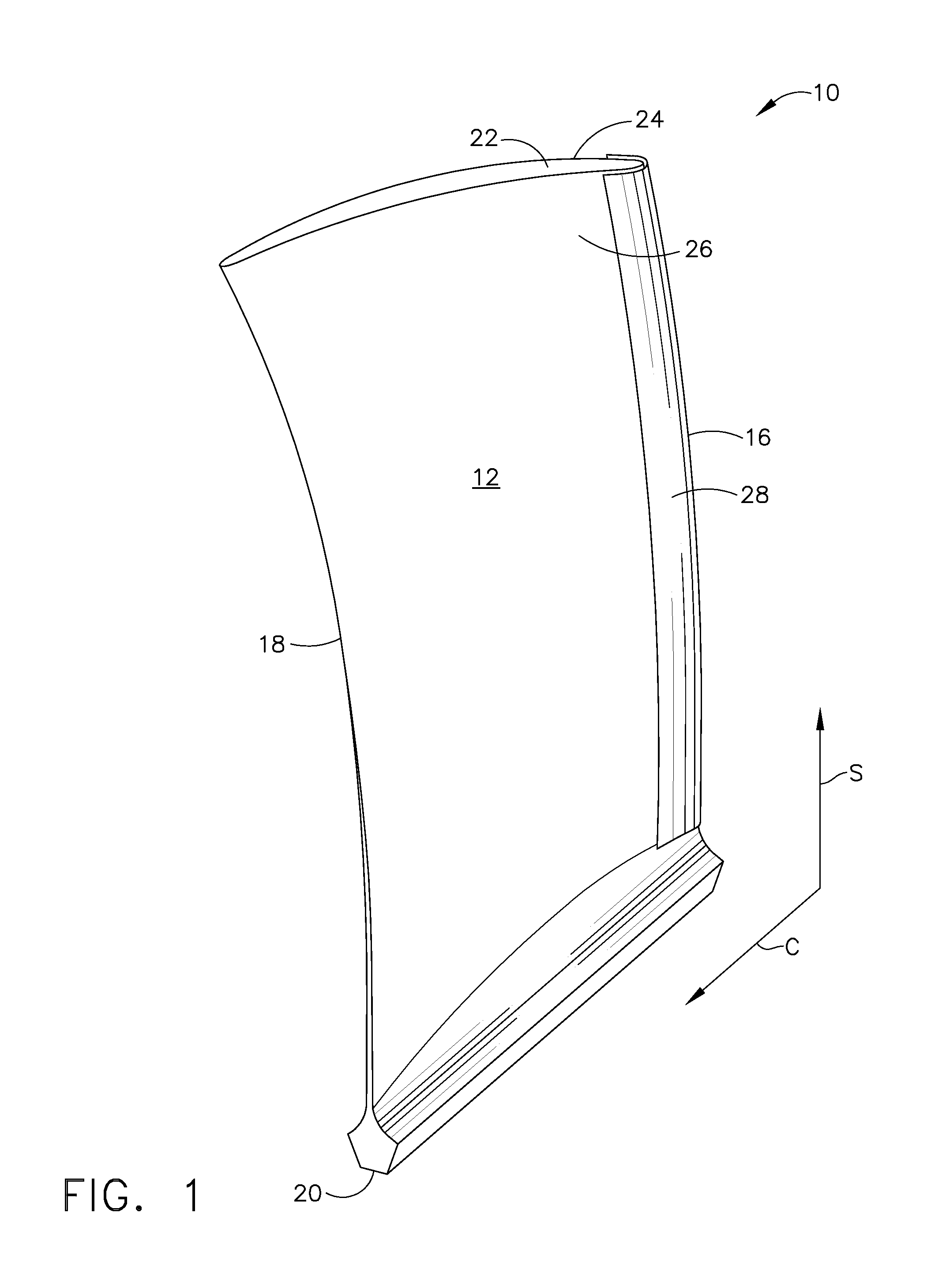
[0015]FIG. 1 is a composite fan blade 10 for a gas turbine engine having a composite airfoil 12 generally extending in a chordwise direction C from a leading edge 16 to a trailing edge 18. Airfoil 12 extends radially outward in a spanwise direction S from a root 20 to a tip 22 generally defining its span and having a suction side 24 and a pressure side 26. Airfoil 12 can be constructed from plies of composite material as is known in the art. Embodiments herein describe methods and tooling for making a titanium or titanium alloy metal leading edge (MLE) protective strip 28 for adhesion to airfoil leading edge 16. Though embodiments herein focus on composite fan blades, the methods, tooling and MLE protective strips herein are suitable for use with any composite airfoil, including b...


PUM

PropertyMeasurementUnit
Temperatureaaaaaaaaaa
Thicknessaaaaaaaaaa
Thicknessaaaaaaaaaa

Abstract

Tooling systems including a mandrel for receiving, and providing shape to, a metallic deposit applied using a high temperature additive manufacturing device; a metallic cladding applied to the mandrel for reducing contamination of the metallic deposit; and at least one cooling channel associated with the mandrel for removing heat from the system.

Description

TECHNICAL FIELD[0001]Embodiments described herein generally relate to high temperature additive manufacturing systems for making near net shape airfoil leading edge protection and tooling systems for use therewith.BACKGROUND OF THE INVENTION[0002]Many modern turbine engine airfoils, such as blades and vanes, are constructed of a composite laminate or molded fiber. Airfoil metal leading edge (herein “MLE”) protective strips can be used to protect composite airfoils from impact and erosion damage that can often occur in the engine environment. In conventional practices, a v-shaped protective metallic strip is often wrapped around the leading edge and sides of the airfoil to provide such protection.[0003]While MLE protective strips can be made from a variety of materials, titanium and titanium alloys are often utilized due to their favorable weight and mechanical properties. However, hot forming methods must be used to fabricate these titanium components. Hot forming typically involves...

Claims


Application Information

Patent Timeline
IPC IPC(8): C23C16/00B22D27/04B23K9/16B23K20/10B23K20/04B05C5/00C23C14/34B23K15/00B23K26/34
CPCB22F5/04B23K35/0244B23K9/048B23K10/027B23K15/0086B23K26/34B23K37/06B23K2201/001B23K2201/06B23P15/04C23C4/08F04D29/023F04D29/324B22F2998/00B23K26/345B23K26/328B23K26/3273B23K26/3266B22F2003/1056B23K26/3206B23K26/3213B23K26/322B22F3/003B22F3/105B22F3/115B22F3/008F05D2240/303B23K26/32B23K26/342F05D2300/5024F05D2230/31F05D2300/133B23K2101/001B23K2101/06B23K2103/04B23K2103/08B23K2103/12B23K2103/14B23K2103/16B23K2103/50B23K2103/52B33Y80/00Y02P10/25B22F12/20B22F10/25
Inventor PERETTI, MICHAEL W.TRAPP, TIMOTHY
Owner GENERAL ELECTRIC CO
Learn More