Ethanol plant process

Inactive Publication Date: 2009-07-02
CASEY LEONARD RAY
View PDF3 Cites 172 Cited by
  • Summary
  • Abstract
  • Description
  • Claims
  • Application Information

AI Technical Summary

Benefits of technology

[0016]The present invention conserves water by reducing the heat load placed on a cooling tower during the ethanol fuel production process. An air cooler is placed between the ethanol vapor condenser and the cooling tower (preferably as close to the condenser as is physically possible) thereby minimizing process temperature spikes before water enters the cooling tower. This, in turn, shortens the process cycle thereby increasing ethanol production. During certain climactic conditions, the cooling tower may be completely bypassed, thereby conserving more water and increasing ethanol production. The decreased use of water also reduces pollution drift, the risk of spreading airborne pathogens, and electricity consumption.
[0017]On average, three gallons of fresh water are used to produce one gallon of ethanol. A typical ethanol plant producing 100 million gallons of ethanol a year uses approximately 300 million gallons of fresh water per year during the ethanol production process. Furthermore, cooling towers themselves can evaporate approximately 9 gallons of water for every one gallon of ethanol produced. (An ethanol plant producing 47 million gallons of ethanol per year produces a heat load of approximately 42,000 BTU per minute. With a ΔT of approximately 20° and a conversion rate of 500, approximately 420 million BTU are produced per hour. A cooling tower uses approximately 1000 pounds of water to expel 1 million BTU resulting in the use of approximately 420 thousand pounds of water per hour or 50360 gallons of water per hour. Therefore, a plant operating for approximately 8500 hours per year uses approximately 420 million gallons of water per year to produce 47 million gallons of ethanol.) It is estimated that using an air cooled heat exchanger as described herein will reduce water consumption in a typical ethanol plant by approximately 20-25%. It is also estimated that using an air cooled heat exchanger as described herein will increase ethanol production in a typical ethanol plant by 0.5-2% due to increased efficiency of the ethanol plant.

Problems solved by technology

Although cooling towers serve their particular purpose, they have several drawbacks: they do not work properly at very cold temperatures, they are not water conservation friendly, they can spread pollutants over wide areas in the form of evaporated water (drift), they create an increased risk of spreading airborne pathogens, and they use large amounts of electricity to run fans.
This, in turn, shortens the process cycle thereby increasing ethanol production.

Method used


Image

  • Ethanol plant process
  • Ethanol plant process

Examples


Embodiment Construction

[0020]The embodiments discussed herein are merely illustrative of specific manners in which to make and use the invention and are not to be interpreted as limiting the scope of the instant invention.

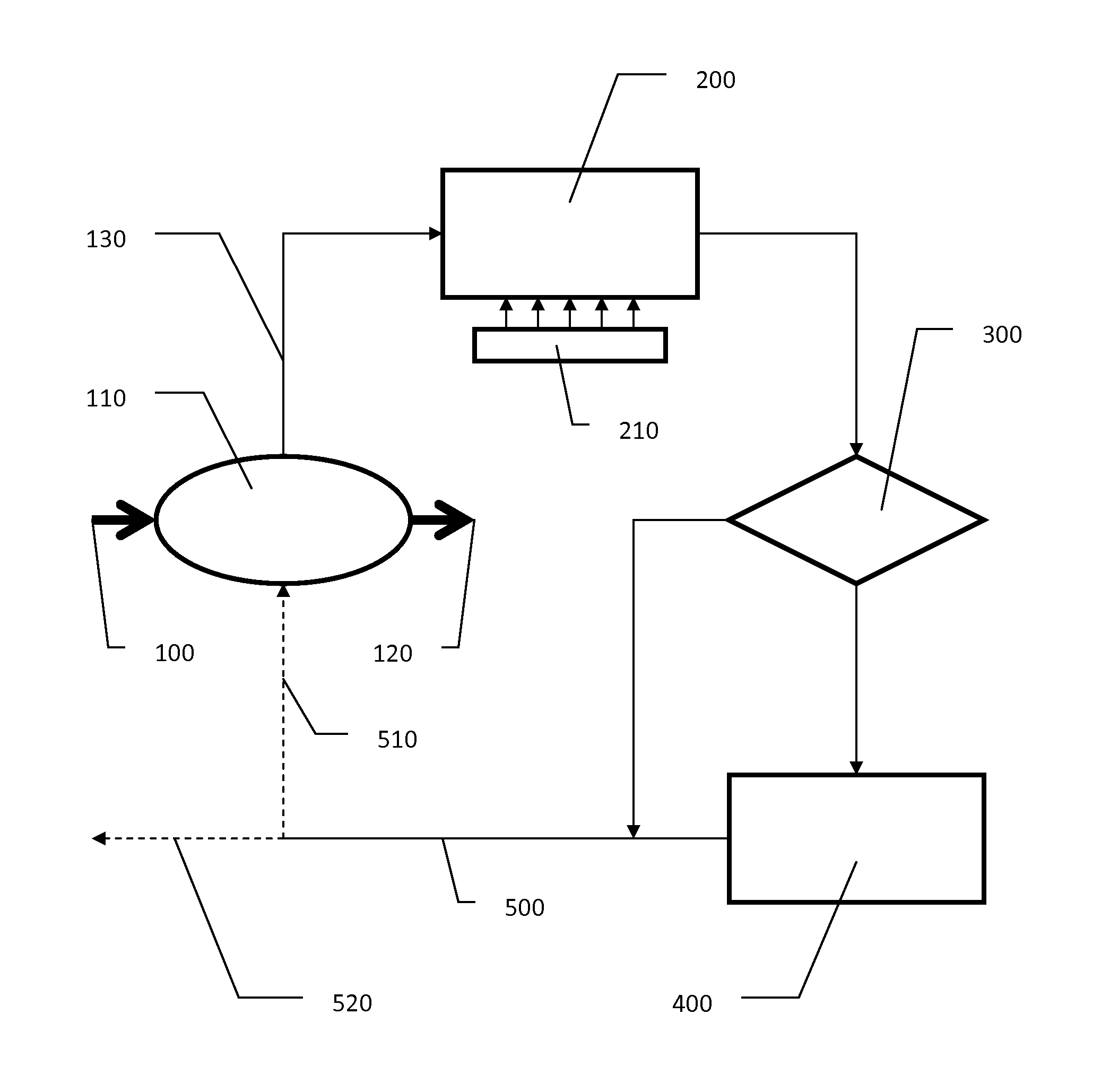
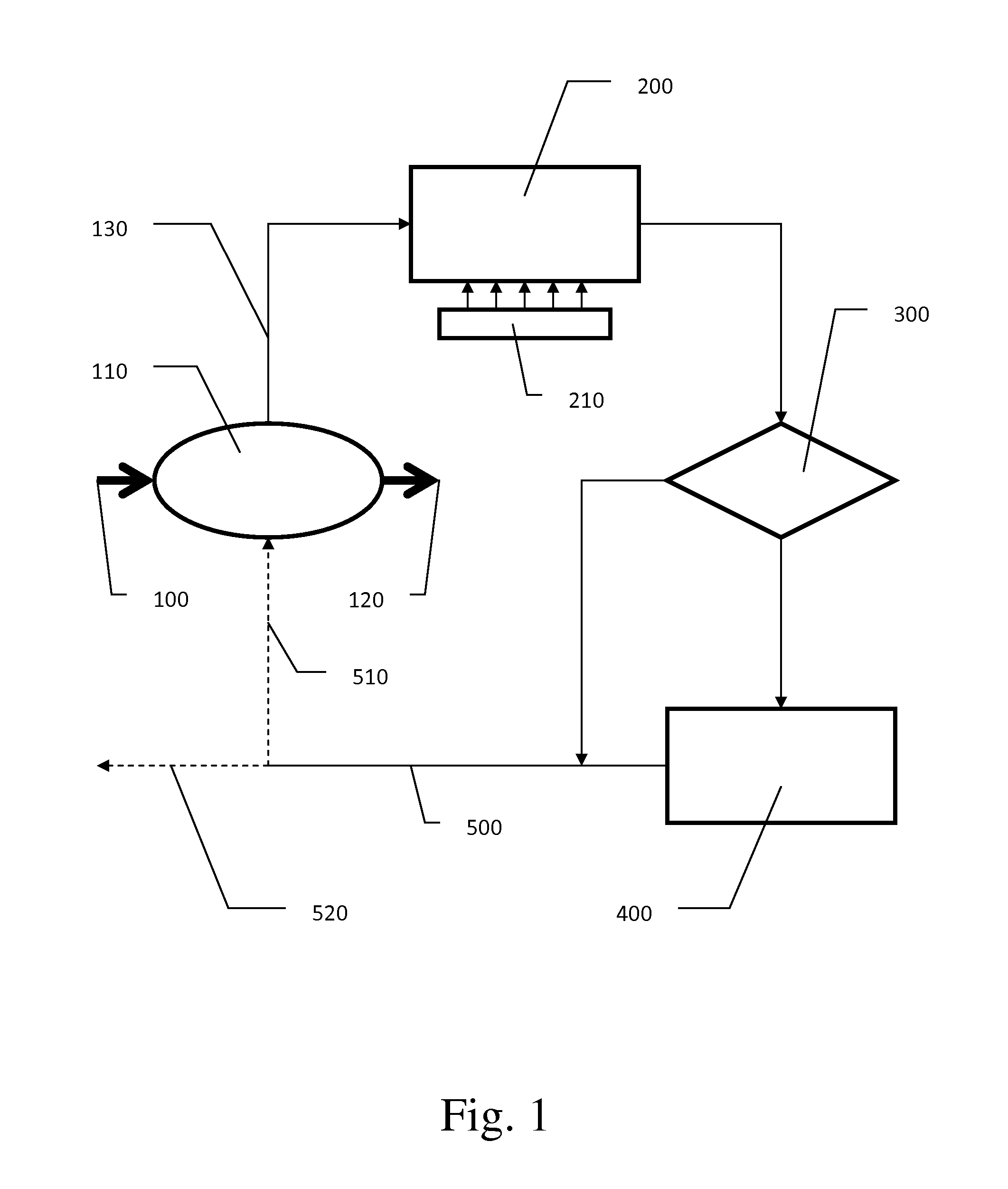
[0021]Referring to the drawing in detail, FIG. 1 illustrates a schematic flowchart of the method as described herein. Ethanol vapor from the plant process 100 is directed into a condenser 110 (shell & tube, etc.) wherein the ethanol vapor is condensed into liquid ethanol (by exchanging heat with water) and directed out of the condenser for further plant processing 120. The heated water 130 leaves the condenser and is directed through an air cooled heat exchanger 200 wherein the heated water is cooled by exchanging heat with the air. In the preferred embodiment, the air cooled heat exchanger is placed as close to the condenser as is physically possible. Air circulation over the air cooled heat exchanger may be increased by the addition of a fan or fans 210.

[0022]After passing through the ...


PUM

PropertyMeasurementUnit
Temperatureaaaaaaaaaa

Abstract

The present invention conserves water by reducing the heat load placed on a cooling tower during the ethanol fuel production process. An air cooler is placed between the ethanol vapor condenser and the cooling tower thereby minimizing process temperature spikes before water enters the cooling tower. This, in turn, shortens the process cycle thereby increasing ethanol production. During certain climactic conditions, the cooling tower may be completely bypassed, thereby conserving more water and increasing ethanol production.

Description

BACKGROUND OF THE INVENTION[0001]1. Field of the Invention[0002]The present invention relates to ethanol fuel plants and ethanol fuel plant processes.[0003]2. Description of Related Art[0004]Ethyl alcohol, the same alcohol found in alcoholic beverages, may also be used as a bio-fuel alternative to gasoline. The increasing cost of gasoline is making “ethanol fuel” a viable alternative energy source to fossil fuels and their derivatives. Because it is easy to manufacture and process, and can be made from common materials, ethanol fuel is steadily becoming a promising alternative to gasoline throughout much of the world.[0005]Ethanol can be mass-produced by fermentation of sugar or by hydration of ethylene from petroleum and other sources. Current interest in ethanol mainly lies in bio-ethanol, produced from the starch or sugar in a wide variety of crops. There are concerns relating to large amount of arable land required for crops, as well as the energy and pollution balance of the et...

Claims


Application Information

Patent Timeline
IPC IPC(8): C07C29/80
CPCC07C29/80C12C11/02C07C31/08
Inventor CASEY, LEONARD RAY
Owner CASEY LEONARD RAY
Why Eureka
Try Eureka