OLED device with cyclobutene electron injection materials
- Summary
- Abstract
- Description
- Claims
- Application Information
AI Technical Summary
Benefits of technology
Problems solved by technology
Method used
Image


Examples
example 1
Synthesis of Inventive Compound Inv-1
[0335]Inv-1 was synthesized as outlined in Scheme 1 and described below.
[0336]1,1-Diphenyl-3-(3-pyridyl)-2-propyn-1-ol(compound 1, 7.5 g, 26 mMole) was suspended in dichloromethane (50 mL) and tetrahydrofuran (30 mL), and the mixture was stirred under a nitrogen atmosphere and gently heated to achieve a solution. To this solution was then added triethylamine (5.11 mL, 36 mMole) and 4-dimethylaminopyridine (100 mg) and the solution was cooled to below 0° C. in an ice / acetone bath. Methanesulfonyl chloride (3.12 mL, 36 mMoles) was then added dropwise at such a rate as to maintain the temperature in the 0 to 5° C. range. After this addition, the temperature was allowed to fall to −5° C. and the reaction mixture was stirred at this temperature for 15 min. and then finally stirred for another 15 min. without the cooling bath. During this time, the temperature of the reaction mixture increased to room temperature. Toluene (100 mL) was then added togeth...
example 2
Electrochemical Redox Potentials and Estimated Energy Levels
[0337]LUMO and HOMO values are typically estimated experimentally by electrochemical methods. The following method illustrates a useful way to measure redox properties. A Model CH1660 electrochemical analyzer (CH Instruments, Inc., Austin, Tex.) was employed to carry out the electrochemical measurements. Cyclic voltammetry (CV) and Osteryoung square-wave voltammetry (SWV) were used to characterize the redox properties of the compounds of interest. A glassy carbon (GC) disk electrode (A=0.071 cm2) was used as working electrode. The GC electrode was polished with 0.05 μm alumina slurry, followed by sonication cleaning in Milli-Q deionized water twice and rinsed with acetone in between water cleaning. The electrode was finally cleaned and activated by electrochemical treatment prior to use. A platinum wire served as counter electrode and a saturated calomel electrode (SCE) was used as a quasi-reference electrode to complete a ...
example 3
Preparation of Blue-Light Emitting OLED Devices 3.1 through 3.12
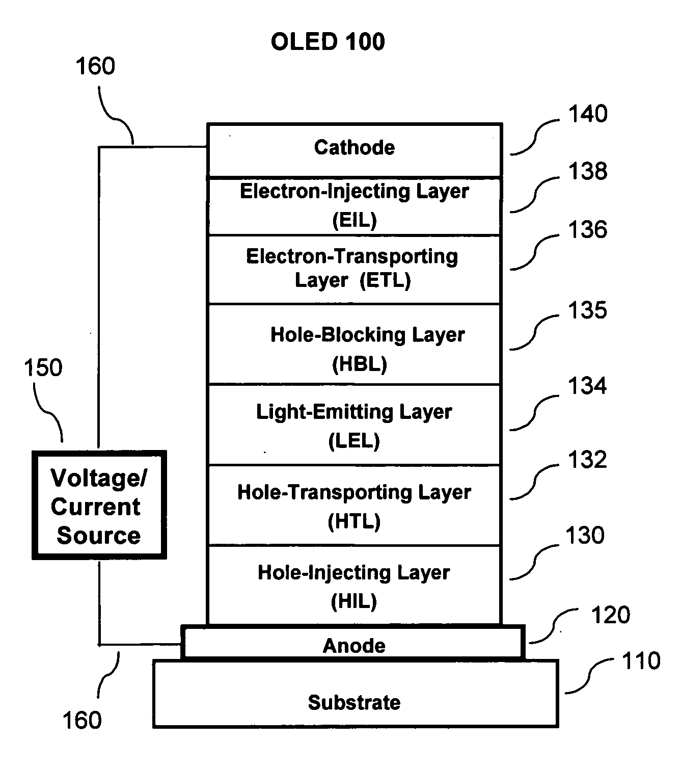
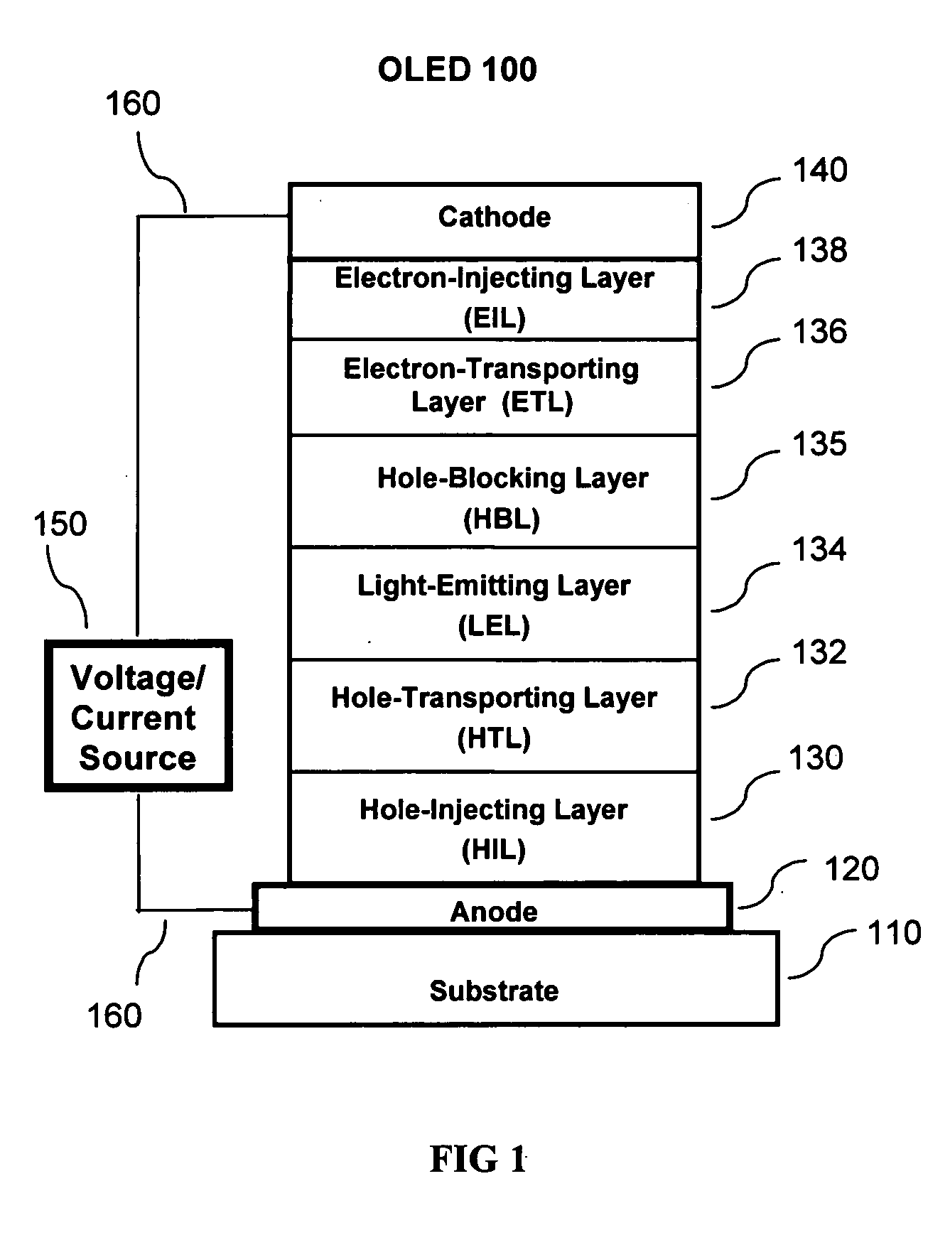
[0342]A series of OLED devices (3.1 through 3.6) were constructed in the following manner:
[0343]1. A glass substrate coated with an 85 nm layer of indium-tin oxide (ITO), as the anode, was sequentially ultrasonicated in a commercial detergent, rinsed in deionized water and exposed to oxygen plasma for about 1 min.
[0344]2. Over the ITO was deposited a 1 nm fluorocarbon (CFx) hole-injecting layer (HIL) by plasma-assisted deposition of CHF3 as described in U.S. Pat. No. 6,208,075.
[0345]3. Next a layer of hole-transporting material 4,4′-Bis[N-(1-naphthyl)-N-phenylamino]biphenyl (NPB) was deposited to a thickness of 95 nm.
[0346]4. A 20 nm light-emitting layer (LEL) corresponding to the host material P-4 and 1.5% by volume of FD-54 was then deposited.
[0347]5. An electron-transporting layer (ETL) consisting of a mixture of isomeric compounds FA-2 and FA-3 (60 / 40 ratio) at a thickness as shown in Table 2 was vacuum-deposited ov...
PUM
| Property | Measurement | Unit |
|---|---|---|
| Energy | aaaaa | aaaaa |
Abstract
Description
Claims
Application Information
 - Generate Ideas
- Intellectual Property
- Life Sciences
- Materials
- Tech Scout
- Unparalleled Data Quality
- Higher Quality Content
- 60% Fewer Hallucinations
Browse by: Latest US Patents, China's latest patents, Technical Efficacy Thesaurus, Application Domain, Technology Topic, Popular Technical Reports.
© 2025 PatSnap. All rights reserved.Legal|Privacy policy|Modern Slavery Act Transparency Statement|Sitemap|About US| Contact US: help@patsnap.com