Thermal spray formation of polymer coatings

a technology of polymer coating and thermal spray, which is applied in the field of thermal spray formation of polymer coating, can solve the problems of solvent spray methods that release toxic (volatile organic compounds, voc's) to the environment, and the background art methods and systems for applying polymer film coatings have serious limitations, so as to prevent the exposure of polymer materials

Inactive Publication Date: 2010-01-14
SCOTT COGUILL L +4
View PDF19 Cites 15 Cited by
  • Summary
  • Abstract
  • Description
  • Claims
  • Application Information

AI Technical Summary

Benefits of technology

[0009]A purpose of the invention is to provide means for spray forming of polymer coatings on a variety of substrates using eclectically heated gas stream. Another purpose is to enable use of a dray polymer powder without solvent dilution. Another purpose is to provide means for melting the polymer onto the surface of the substrate during the spray process. Another purpose is to prevent exposure of the polymer materials to temperatures in excess of their degradation temperatures. Another purpose is to avoid the use of thermal spray methods utilizing plasma or flame that can cause polymer overheating and degradation.
[0015]In a preferred embodiment, the apparatus is equipped with an ultraviolet light source (350-420 nanometer wave length) to enable the curing of ultraviolet-light-curable polymer powders as they are being deposited as molten films. Ultraviolet (UV) light has limited penetration, especially of dark tinted polymers. This embodiment allows UV light exposure, complete penetration of the thin molten film and subsequent cure during each pass of the apparatus. This removes limitations on film thickness typically associated with UV-light-curable polymers. In another preferred embodiment, the apparatus is equipped with an infrared light source to aid in the curing of thermoset polymer powders as they are being deposited as molten films.
[0017]In preferred embodiments, careful design consideration is given to the gas velocity at the nozzle exit and gas velocity / temperature as the polymer particle laden plume impinges upon the substrate being coated. When the polymer particles are initially injected into the hot gas plume there exist a high relative velocity difference between the fast moving gas and the relatively slow moving polymer particles. This creates a condition of high convective heat transfer between the hot gas and the lower temperature particles. This condition allows the polymer particles to quickly heat and soften / melt. As the particle accelerates to match the velocity of the hot gas, the heat transfer condition becomes less favorable. Additionally, the hot gas plume temperature decreases as the plume expands and entrains ambient air. Consequently, the polymer particles, now in the form of molten or softened droplets, do not cool as fast as they heated and can retain their temperature as they impact the substrate. At this point, the gas plume that strikes the substrate is cooler then the molten polymer particles being conveyed. This allows heat sensitive substrates to be coated even when the molten polymer has a temperature in excess of the upper allowed substrate temperature. On the other hand, larger partially molten particles that stick to the substrate can be heated to a higher temperature by hot convective gas and successfully fused / consolidated with rest of coating on the substrate. The preferred particle size distribution of powder that is sprayed using this device is in the range of about 30 microns to about 300 microns.
[0018]One of the advantageous features of preferred embodiments of the process is low heat input to the substrate due to negligible thermal mass (about 10-60 Jules per particle) of the micron sized droplets. This feature allows the deposition of high melting temperature polymers (greater than 200° C.) and low melting temperature metals (less than 600° C.) over heat sensitive substrates such as electronics and even paper without damaging the underlying substrate surface.

Problems solved by technology

Background art methods and systems for applying polymer film coatings have serious limitations.
Solvent spray methods often release toxic (volatile organic compounds, VOC's) to the environment.
Background art thermal spray methods which rely on hot combustion gas (greater than 1,500° C.) or hot plasma gas (greater than 10,000° C.) can result in overheating of polymer particles in flight and also can cause overheating of polymer layers deposited in previous spray passes.
Excessive heating of polymers by these processes can cause oxidation and / or thermal degradation of the sprayed material resulting in inferior properties and shorter service life.
The methods that rely on combustion gases are inherently less clean due to the exhaust fumes.

Method used


Image

  • Thermal spray formation of polymer coatings
  • Thermal spray formation of polymer coatings
  • Thermal spray formation of polymer coatings

Examples


Embodiment Construction

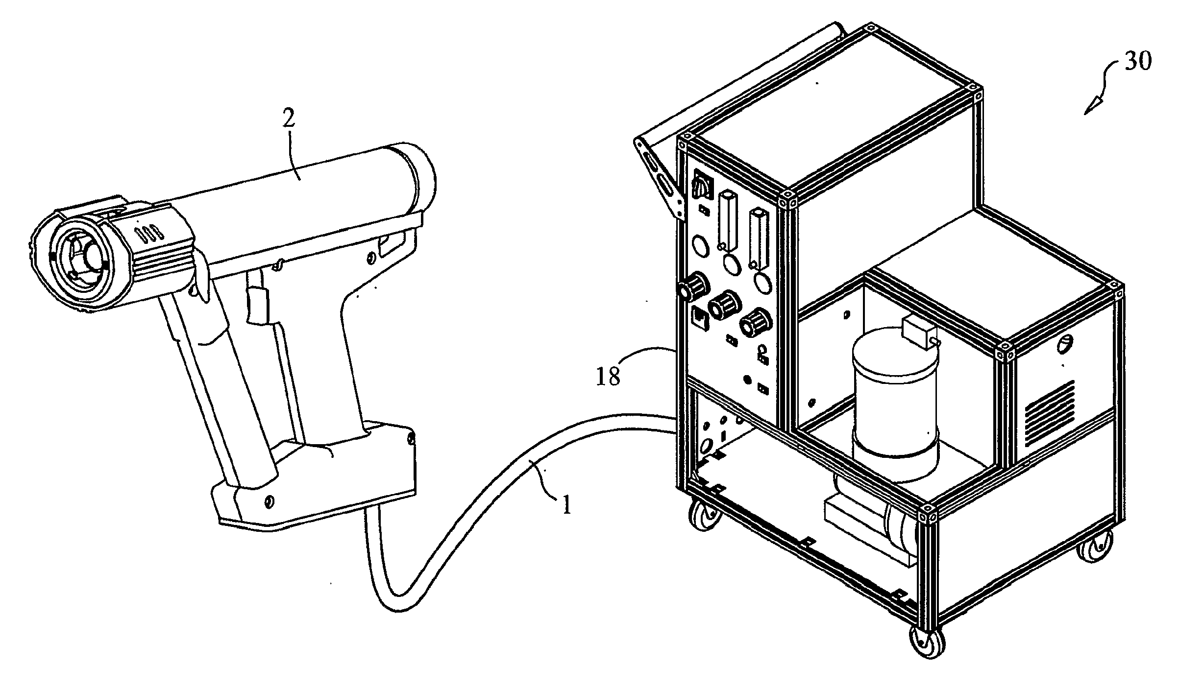
[0083]Referring to FIGS. 1A, 1B and 1C, schematic diagrams illustrating the operation of preferred embodiments of system 30 are presented. FIG. 1A illustrates changes in convective gas temperature 37, polymer powder particle surface temperature 38 and polymer powder particle core temperature 39 that occur with a polymer powder particle size of less than about 100 micrometers. FIG. 1B illustrates changes in convective gas temperature 37, polymer powder particle surface temperature 38 and polymer powder particle core temperature 39 that occur with polymer powder particle sizes that range from about 100 micrometers to about 300 micrometers. FIG. 1C illustrates changes in convective gas temperature 37, polymer powder particle surface temperature 38 and polymer powder particle core temperature 39 that occur with a polymer powder particle size of greater than about 300 micrometers.

[0084]In these diagrams, applicator head 36 discharges spray 32 comprised of hot air jet 13 and impinging mat...


PUM


Abstract

A system (30) and method for fluidizing a polymer powder (11) to be sprayed, metering the material (12) and mixing it with a heated carrier-gas stream (13) to produce a spray (32), and using the spray (32) to transport the material (12) to a substrate (34) and radiant an convective heating of the material (12) during transport to achieve melting of the polymer powders (11).

Description

STATEMENT REGARDING FEDERALLY SPONSORED RESEARCH OR DEVELOPMENT[0001]The U.S. Government has a paid-up license in this invention and the right in limited circumstances to require the patent owner to license others on reasonable terms as provided for by the terms of Contract No. NAS3-02164 awarded by the National Aeronautics and Space Administration.CROSS-REFERENCE TO RELATED APPLICATIONS[0002]Not ApplicableINCORPORATION-BY-REFERENCE OF MATERIAL SUBMITTED ON A COMPACT DISC[0003]Not ApplicableBACKGROUND OF THE INVENTION[0004]This invention relates to the formation of polymer coatings. In particular, the invention relates to the use of a thermal spray apparatus and polymer powders to create sprayable polymer coatings.[0005]The background art is characterized by U.S. Pat. Nos. 3,677,471; 3,958,758; 4,065,057; 4,835,022; 4,911,956; 5,041,713; 5,285,967; 5,718,863; 6,074,194; 6,488,773 and 6,793,976; and by U.S. Patent Application No. 2002 / 0110682; the disclosures of which patents and pat...

Claims


Application Information

Patent Timeline
IPC IPC(8): B05D1/12B05B1/24B05B7/16
CPCB05D1/04B05D3/067B05D3/0413B05D1/12
Inventor SCOTT, COGUILL L.GALBRAITH, STEPHEN L.TUSS, DARREN L.IVOSEVIC, MILANFARRAR, LAWRENCE C.
Owner SCOTT COGUILL L
Why Eureka
Try Eureka