
Structured coatings for implants and process for the preparation thereof

Active Publication Date: 2009-12-24
BIOCER ENTWICKLUNGS
View PDF4 Cites 55 Cited by
  • Summary
  • Abstract
  • Description
  • Claims
  • Application Information

AI Technical Summary

Benefits of technology

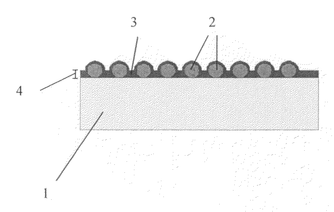
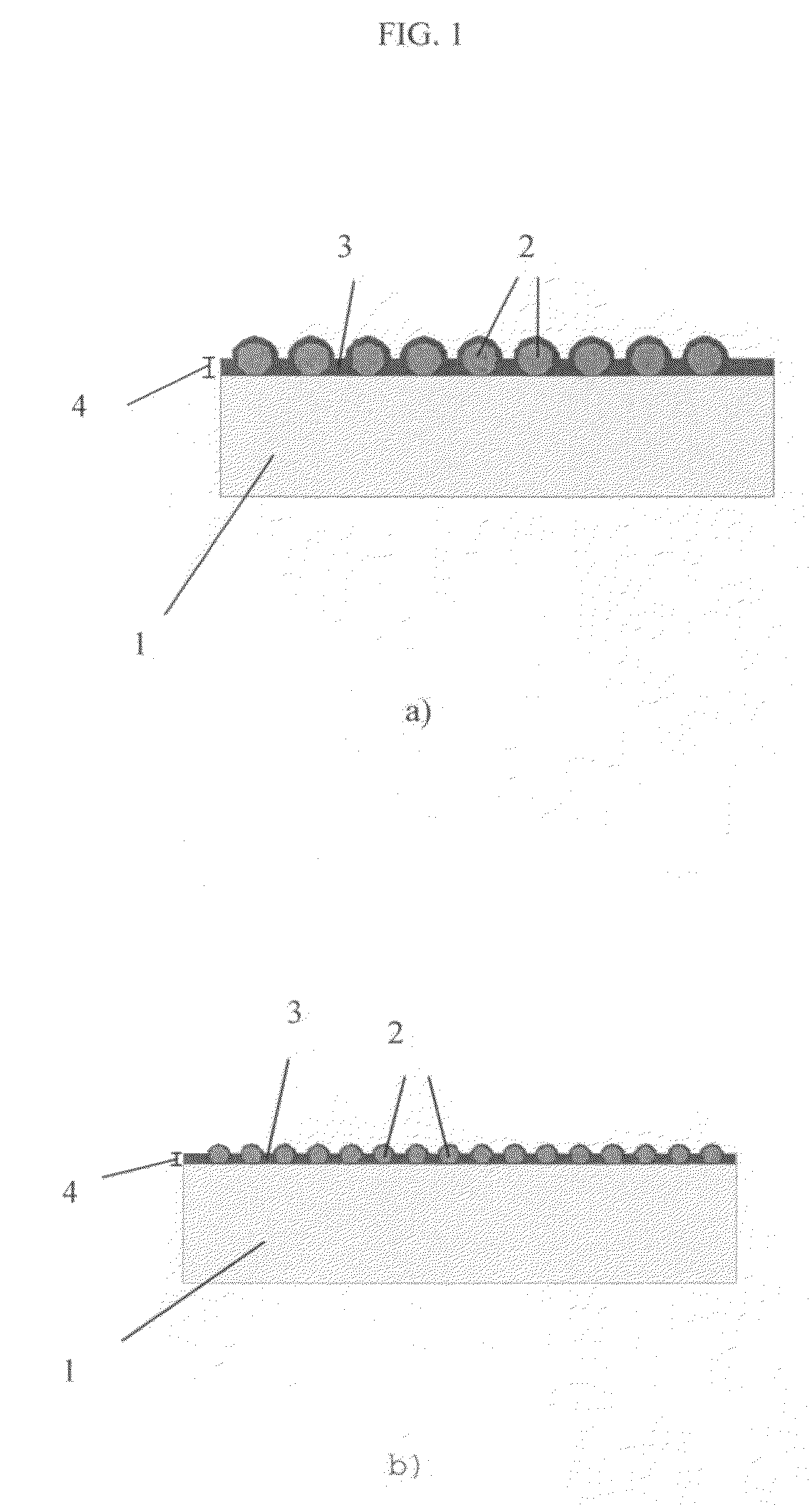
[0035]The thickness of the coating according to the invention is in the range of several hundred nanometres, preferably approximately 50 to 10,000 nm, preferably 100 to 5,000 nm, more preferably 150 to 1,500 nm. The particular thin nature of the layer and the low proportion of filler material in the layer enable the adhesion of the layer to the substrate to be improved significantly.
[0062]The process according to the invention enables the concentration of active substances eluted from the coating to be precisely established by dilution or by providing a plurality of layers. Providing a plurality of layers can boost the effect of the coating, since a greater amount of active substances can be provided. A single and / or two-layer coating is preferred.

Problems solved by technology

However, the use thereof is limited to metal ions, the organic salts of which can be dissolved in a sol.
This granular material can be coated onto an implant but must, however, be applied by an expensive method, a plasma spraying method for example.
It is also not possible to texture the surface in a targeted manner.
However, this material has the drawback that it has a reduced stability in storage on account of the organic components and is difficult to sterilise with the γ-radiation sterilisation method which is conventional in the medical field.
A subsequent sterilisation procedure in hospital is also hindered by the fact that heating the material to 132° C. results in degradation of the organic components.
Furthermore, an active substance, such as an antibiotic or a polymer, present in the material can be damaged or immobilised by radicals produced by γ-radiation.
In this application, the metal salt used is homogeneously and completely dissolved in the sol-gel matrix and is not present as solid particles, and it is therefore not possible to texture the surface.
This material is not suitable for coating an implant due to the high porosity of the material.
All the aforementioned processes have the drawback that it is not possible to texture the surface in a purposeful manner and to adjust the release of the active substance.

Method used


Image

  • Structured coatings for implants and process for the preparation thereof
  • Structured coatings for implants and process for the preparation thereof
  • Structured coatings for implants and process for the preparation thereof

Examples


example 1

Coating with a Hydroxyl Apatite Filler

[0073]69.5 g of tetrabutoxy titanate were dissolved in 500 g of n-butanol at room temperature and were stirred for 2 hours. 17.1 g (corresponding to 3% by weight) of commercial calcium phosphate powder (Merck, D50<2 μm) was subsequently added in portions, based on the total weight of the sol provided (569.5 g). 1% by weight of a dispersant (DB194, anhydrous; Byk Chemie, Wesel) was added for the purposes of dispersion and was stirred for a further 2 hours.

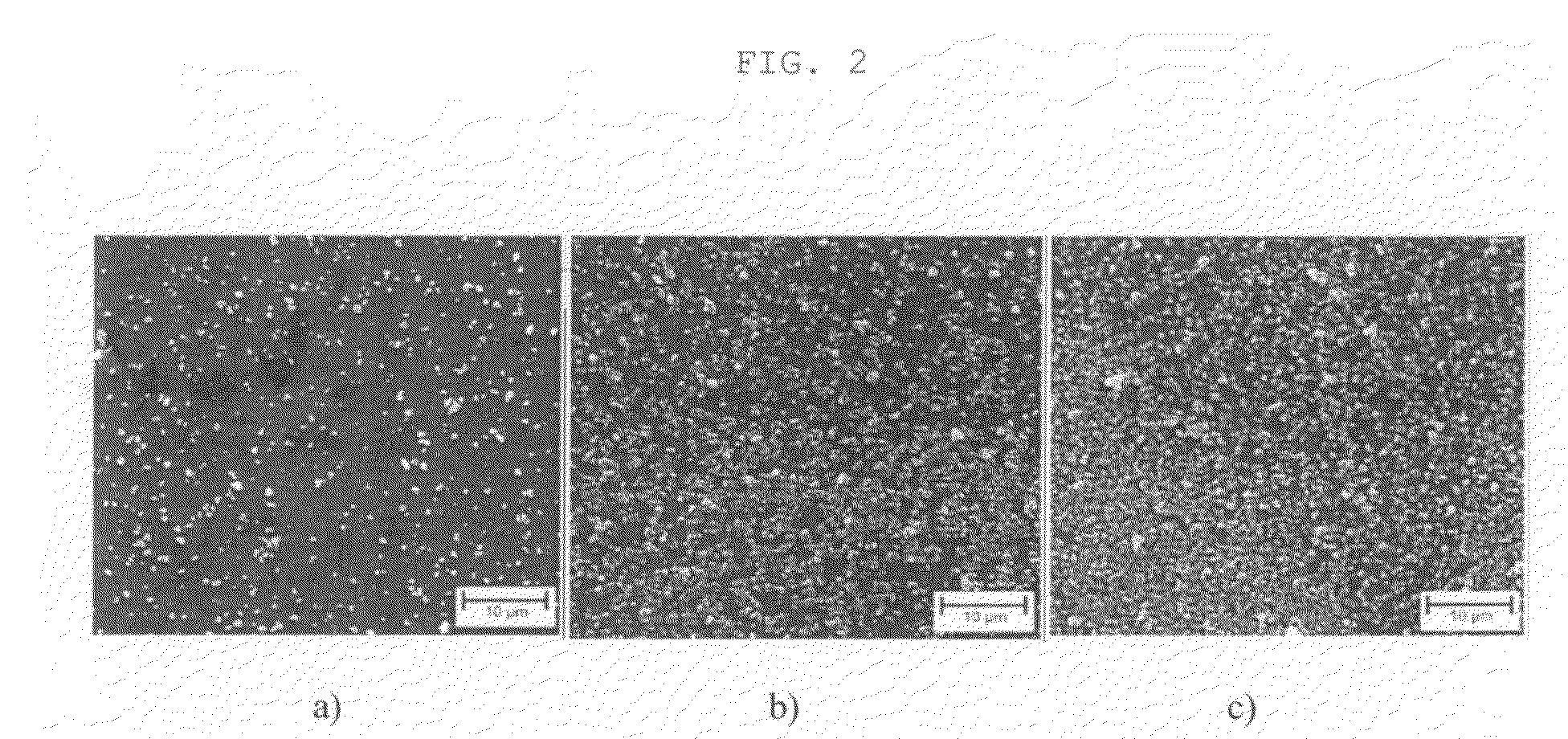
[0074]The glass test specimen was subsequently coated by dipping said test specimen with a withdrawal speed of 1.5 mm / s. It was subsequently dried at room temperature for 1 hour and the coating was ceramised (calcined) at 500° C. for 10 minutes. An electron microscope image of the coating is shown in FIG. 2b).

[0075]Preparations containing 1% by weight and 8% by weight of calcium phosphate powder instead of 3% calcium phosphate powder were produced in accordance with the above description and wer...

example 2

Coating with a Titanium Oxide Filler

[0077]41.7 g of tetrabutoxy titanate were dissolved in 300 g of n-butanol at room temperature and were stirred for 2 hours. 1.71 g (corresponding to 0.5% by weight), 10.26 g (corresponding to 3% by weight), and 20.52 g (corresponding to 6% by weight), based on the total weight of the sol provided (341.7 g), of commercial titanium oxide powder (Alfa Aesar, Karlsruhe; D50: 0.3 μm) were added in portions. 1% by weight of a dispersant (DB194, anhydrous; Byk Chemie, Wesel) was added for the purposes of dispersion and was stirred for a further 2 hours.

[0078]The glass test specimen was subsequently coated by means of dipping with a withdrawal speed of 1.5 mm / s. It was subsequently dried at room temperature for 1 hour and the coating was ceramised at 500° C. for 10 minutes. Coatings were applied to TiAl6V4, titanium, a stainless steel, zirconium oxide and the plastics material polymethyl methacrylate (PMMA) in accordance with Example 2 specified above. Th...

example 3

Description of the Mode of Action

[0079]In order to demonstrate the mode of action of the powder-filled coating, glass substrates (plates, diameter 14.5 mm) were provided with coatings in accordance with Example 1 which contained different amounts of commercial calcium powder (Merck, D50<2 μm). The release of calcium under physiological conditions was determined on the one hand and the cell growth on the surfaces obtained was determined as a function of the powder filling on the other.

Calcium Content Measurement:

[0080]The calcium concentration was determined by means of a photometric test. This involves the formation of a complex by the reaction of o-cresolphthalein complexone (CPC, Fa. Fluka) with calcium at an alkaline pH. The purple colour of the colour complex formed is measured absorptively at 575 nm. The CPC reagent is prepared as follows: 625 mg of 8-hydroxy quinoline (Fluka) were dissolved in 25 ml dimethyl sulphoxide (Serva), then 10 mg o-cpc and 250 μl 36% HCl (Fluka) were ...


PUM

PropertyMeasurementUnit
Temperatureaaaaaaaaaa
Lengthaaaaaaaaaa

Abstract

The invention relates to a method for producing a powder-filled ceramic coating made from a precursor ceramic compound (for example, a sol-gel), said coating having an advantageous surface roughness and wherein active ingredients may be eluted from the matrix or filler under physiological conditions and to an implant which can be produced according to the claimed method.

Description

[0001]The present invention relates to a process for the preparation of a powder-filled ceramic coating on an implant, and to a coated implant.BACKGROUND OF THE INVENTION AND PRIOR ART[0002]The surface properties of an implant are crucial to the bioacceptability and the biocompatibility of the implant. Firstly, the texture or morphology of the surface is crucial for the growth of new cells on the implant. Secondly, the growth of desired cells can be encouraged by releasing active substances, or the growth of undesirable cell clusters, such as introduced bacteria, which may lead to an infection or even cause the implant to be rejected, can be inhibited.[0003]For these reasons, coatings which are produced in sol-gel processes and release active substances have been developed in the prior art. This release of active substances may have an antibacterial effect for example, as disclosed in DE 10243132. However, the use thereof is limited to metal ions, the organic salts of which can be d...

Claims


Application Information

Patent Timeline
IPC IPC(8): A61C8/00B05D3/00A61F2/28A61F2/06A61F2/18A61F2/02A61F2/24A61M27/00A61M25/00
CPCA61L27/306A61L27/32A61L27/60A61L27/46A61L27/56A61L27/446
Inventor HEIDENAU, FRANKZIEGLER, GUNTER
Owner BIOCER ENTWICKLUNGS
Learn More