
Capped polyurethane prepolymers and heat-curable epoxy resin compositions

a technology of epoxy resin and prepolymer, which is applied in the field of impact modifiers, can solve the problems of weak low-temperature unsatisfactory, and damage to bonding, and achieve the effect of improving the impact resistance of epoxy resin compositions

Inactive Publication Date: 2009-10-22
SIKA TECH AG
View PDF34 Cites 54 Cited by
  • Summary
  • Abstract
  • Description
  • Claims
  • Application Information

AI Technical Summary

Benefits of technology

[0008]It is therefore an object of the present invention to provide impact modifiers which, when compared with the impact modifi

Problems solved by technology

Epoxy resin compositions in particular generally have high mechanical strengths but are very brittle, and this means that when the cured epoxy resin is subject to an impact force, for example one arising in a vehicle collision, it fractures, and the bond is therefore destroyed.
However, these epoxy resin compositions exhibit weaknesses in low-temperature impact resistance (<0° C.).
These epoxy resin compositions have improved low-temperature impact resistance when compared with those comprising phenol-terminated polyurethane prepolymers, but are still not ideal.

Method used


Image

  • Capped polyurethane prepolymers and heat-curable epoxy resin compositions
  • Capped polyurethane prepolymers and heat-curable epoxy resin compositions
  • Capped polyurethane prepolymers and heat-curable epoxy resin compositions

Examples


examples

[0161]Some examples will be indicated below, providing further illustration of the invention, but not in any way intended to restrict its scope. The raw materials used in the examples are listed in table 1.

TABLE 1Raw materials used.Raw materials usedSupplierD.E.R. ™ 330 (bisphenol A diglycidyl ether =Dow“DGEBA”)D.E.R. 671 (“type 1” solid resin) (EP-Dowequivalent weight 475-550 g / eq)Struktol ® Polydis ® VP-3611 (bisphenol FSchill &diglycidyl ether, modifier nitrile-Seilacherbutadiene rubber) (EEW = 560 g / val))(=“Polydis”)Araldite ® DY-H (hexanediol diglycidylHuntsmanether) (=“DY-H”)Dicyandiamide (=“dicy”)DegussaPoly-THF 2000 (difunctional polybutyleneBASFglycol) (OH-equivalent weight = about 1000g / OH-equivalent)Desmophen 3060 BS (trifunctionalBayerpolypropylene glycol) (OH-equivalentweight = 1000 g / OH-equivalent)Isophorone diisocyanate (=IPDI)Degussa-HülsDiphenylmethylene 4,4′-diisocyanateBayer(=MDI)N-ButylamineBASFε-CaprolactamEMS ChemieCardolite NC-700 (Cardanol) (=“NC”)Cardolite2,...

example of

Production of a Monohydroxylated Epoxide “M1”

[0162]Trimethylolpropane glycidyl ether was produced by the process in U.S. Pat. No. 5,668,227, example 1, starting from trimethylolpropane and epichlorohydrin, using tetramethylammonium chloride and sodium hydroxide solution. The product is yellowish, with an epoxy number of 7.5 eq / kg and with hydroxy group content of 1.8 eq / kg. The HPLC MS spectrum indicates that it is in essence a mixture of trimethylolpropane diglycidyl ether and trimethylolpropane triglycidyl ether. This product was used as M1 in table 2.

Monohydroxylated Epoxide “M2”

[0163]1,3-Bis(4-(2-(4-(oxiran-2-ylmethoxy)phenyl)propan-2-yl)phenoxy)propan-2-ol) (“DGEBA dimer”):

corresponding to the compound of the formula (IX) in which R is methyl. 1,3-Bis(4-(2-(4-(oxiran-2-ylmethoxy)phenyl)propan-2-yl)phenoxy)propan-2-ol) was obtained from technical-grade bisphenol A diglycidyl ether (DGEBA) (Araldite® GY 250, produced by Huntsman), in which it is present to an extent of about 15% ...


PUM

PropertyMeasurementUnit
Temperatureaaaaaaaaaa

Abstract

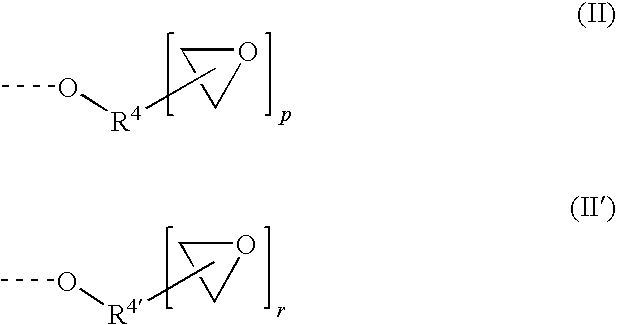
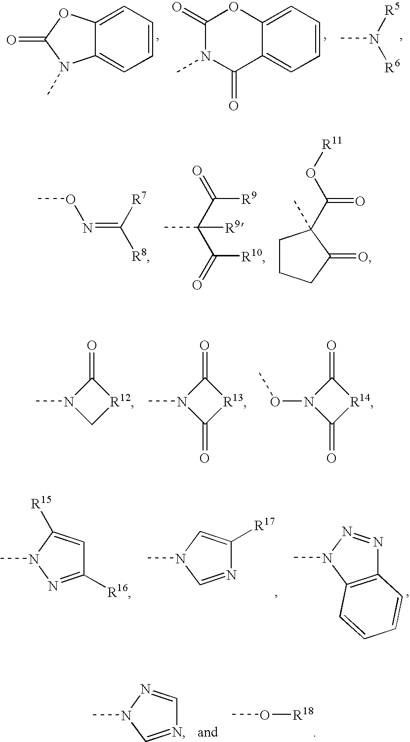
The invention relates to differently blocked polyurethane polymers of formula, to their use as impact resistance modifiers, to heat-curable epoxy resin compositions containing said impact resistance modifiers and to methods for the production of said compositions. The invention also relates to bonding methods using said compositions and to articles produced by said methods.

Description

TECHNICAL FIELD[0001]The invention relates to the field of impact modifiers and to the field of heat-curing epoxy resin compositions.PRIOR ART[0002]Impact modifiers have a long history of use for improving the strength of adhesives subject to impact forces. Epoxy resin compositions in particular generally have high mechanical strengths but are very brittle, and this means that when the cured epoxy resin is subject to an impact force, for example one arising in a vehicle collision, it fractures, and the bond is therefore destroyed.[0003]Liquid rubbers have a relatively long history of use as tougheners. Examples of liquid rubbers used are those based on acrylonitrile / butadiene copolymers, examples being obtainable as Hycar®.[0004]EP-B-0 338 985 describes impact-resistant epoxy resin compositions which comprise not only liquid rubbers based on acrylonitrile / butadiene copolymers but also liquid rubbers based on polyurethane prepolymers, where these have capping by a phenol or by a lact...

Claims


Application Information

Patent Timeline
IPC IPC(8): C08L63/00C08G18/10C08L75/04B32B37/12
CPCC08G18/10C08L75/04C09J163/00C08G18/2845C08G18/285C08L2666/20
Inventor KRAMER, ANDREASFINTER, JURGENRHEINEGGER, URSSCHULENBURG, JAN OLAF
Owner SIKA TECH AG
Learn More