Lens Driving Device

a driving device and lens technology, applied in the direction of printers, instruments, camera focusing arrangement, etc., can solve the problems of difficult to get focused accurately when focusing an object from a short distance, the camera shakes, and the image photographed along with the hand shake may look blurred, etc., to achieve fast responsiveness, good impact resistance, and reliable operation

Active Publication Date: 2014-12-04
LG INNOTEK CO LTD
View PDF9 Cites 77 Cited by
  • Summary
  • Abstract
  • Description
  • Claims
  • Application Information

AI Technical Summary

Benefits of technology

[0033]In a preferred embodiment of the present invention, there is provided a camera module whose operation is fast responsive and is reliable in its operation, which can be obtained in such a way that an auto focusing function is obtained by a lens unit, and a hand-shaking prevention function is obtained by a housing structure.
[0034]The camera module according to a preferred embodiment of the present invention comprises a side spring that has a good impact resistance and a reliable hand-shaking prevention function.
[0035]In a preferred embodiment of the present invention, a product can be easily assembled with the aid of an attractive force because a second coil unit and a magnet unit are arranged on a straight line.

Problems solved by technology

The hand-shaking phenomenon causes such a photographing device to shake.
The images photographed along with a hand-shaking may look blurred, and it is hard to get focused accurately when focusing an object from a short distance.
For this reason, the width of the camera module increases due to its structural characteristic, so it is hard to manufacture a compact-sized and thinner photographing device.
Since the lens in the AF module is configured to substantially move in a horizontal direction, the optical axis of the optical system may be shaken.

Method used


Image

  • Lens Driving Device
  • Lens Driving Device
  • Lens Driving Device

Examples


Embodiment Construction

[0055]The terminology used herein, unless otherwise defined, represents the same meaning as that of the terminology an ordinary person skilled in an art uses, and if the terminology used herein is in conflict with the general terminology, its interpretation is subject to the definition of the present invention.

[0056]The invention described herein is for the purpose of describing particular embodiments only and is not intended to be limiting of the invention. It is noted that the same reference numbers through the specification mean the same components.

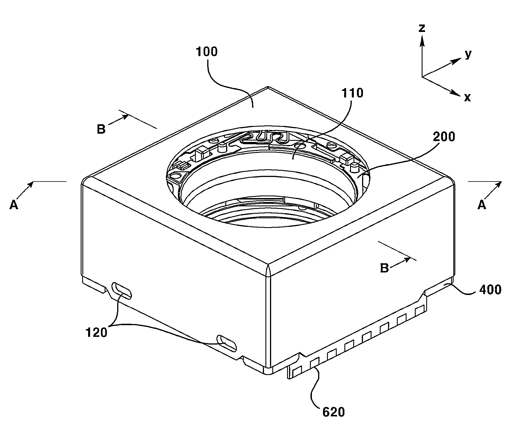
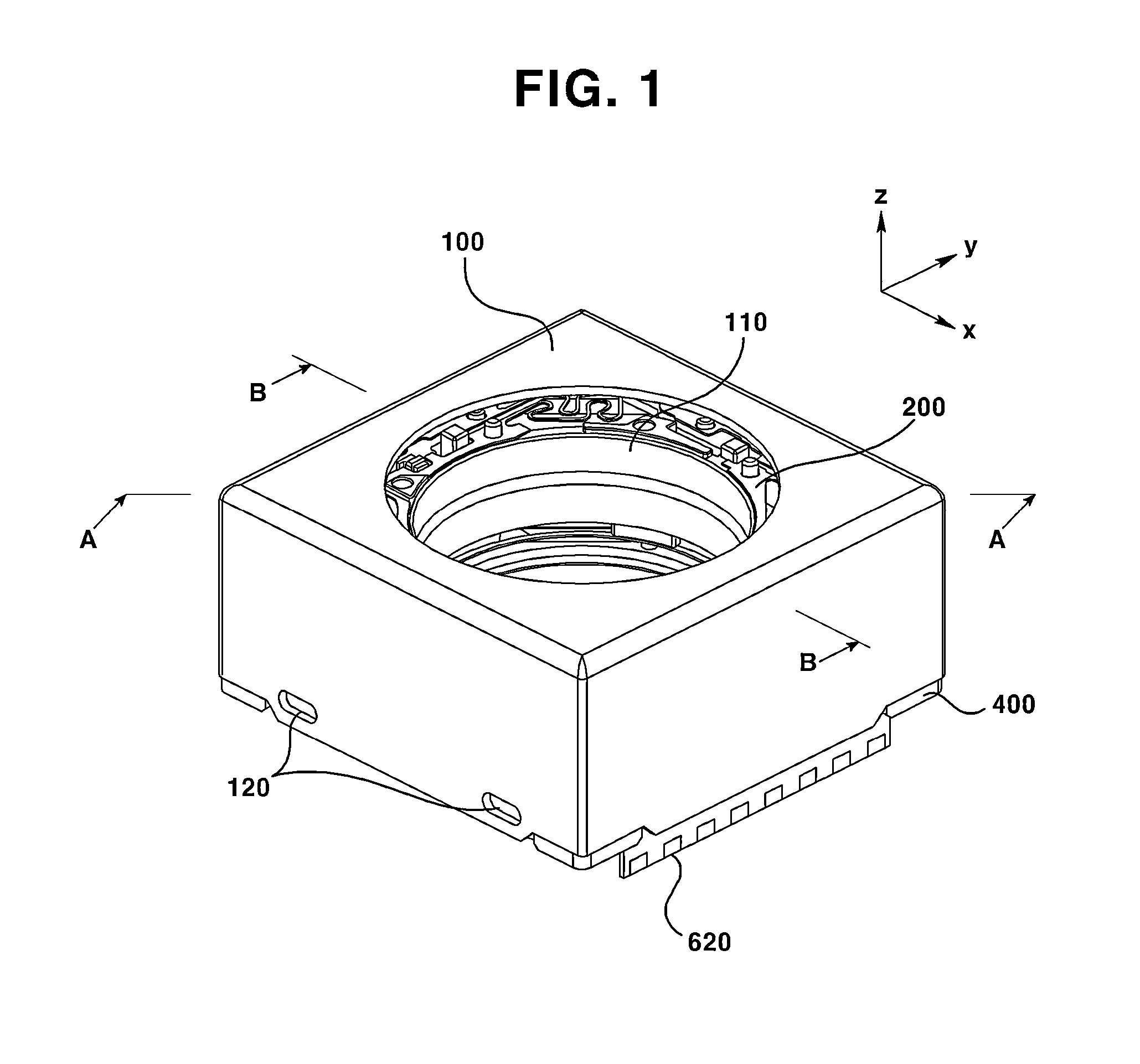
[0057]FIG. 1 is a perspective view illustrating a lens driving motor according to a preferred embodiment of the present invention.

[0058]As shown in FIG. 1, the Z-axis represents an optical axis direction, and the X-axis represents a first direction that is perpendicular to the X-axis direction, and the Y-axis represents a second direction that is perpendicular to each of the Z-axis and the X-axis.

[0059]An preferred embodiment and anoth...


PUM


Abstract

A lens driving device is proposed, including a cover can whose upper side surface includes an opening formed to expose a lens and whose side surface extends from the upper side surface to a base, a base that is secured to the cover can; a housing that is arranged on top of the base and moves in first and second directions that are perpendicular to an optical axis, a bobbin that is housed in the housing and moves in an optical axis direction, an actuator that includes a magnet unit arranged in the housing, a first coil unit arranged in an outer side surface of the bobbin, and a second coil unit that is arranged on top of the base, and a substrate that is disposed between the second coil unit and the base so as to control the first coil unit and the second coil unit.

Description

CROSS-REFERENCE TO RELATED APPLICATIONS[0001]This application claims the benefit under 35 U.S.C. §119 of Korean Application Nos. 10-2013-0082879, filed Jul. 15, 2013, 10-2013-0083294 filed on Jul. 17, 2013, and 10-2013-0061035 filed May 29, 2013, which are hereby incorporated by reference in its entirety.BACKGROUND[0002]1. Field of the Invention[0003]The present invention relates to a lens driving device, and more particularly to a lens driving device whose structure is improved in consideration of a user's hand-shaking correction function and an auto focusing function.[0004]2. Background of the Related Art[0005]A hand shaking phenomenon inevitably occurs when photographing with a photographing device held in hands. The hand-shaking phenomenon causes such a photographing device to shake. The images photographed along with a hand-shaking may look blurred, and it is hard to get focused accurately when focusing an object from a short distance.[0006]In order to reduce the vibrations tha...

Claims


Application Information

Patent Timeline
Patent Type & Authority Applications(United States)
IPC IPC(8): G02B27/64G02B7/09
CPCG02B7/09G02B27/646G02B7/04G03B3/10G03B5/00G03B2205/0015G03B2205/0069G02B7/02G02B13/001H02K41/0356
Inventor YEO, IN JAE
Owner LG INNOTEK CO LTD
Why Eureka
Try Eureka