Airfoil having improved impact and erosion resistance and method for preparing same

Inactive Publication Date: 2006-01-26
GENERAL ELECTRIC CO
View PDF37 Cites 74 Cited by
  • Summary
  • Abstract
  • Description
  • Claims
  • Application Information

AI Technical Summary

Benefits of technology

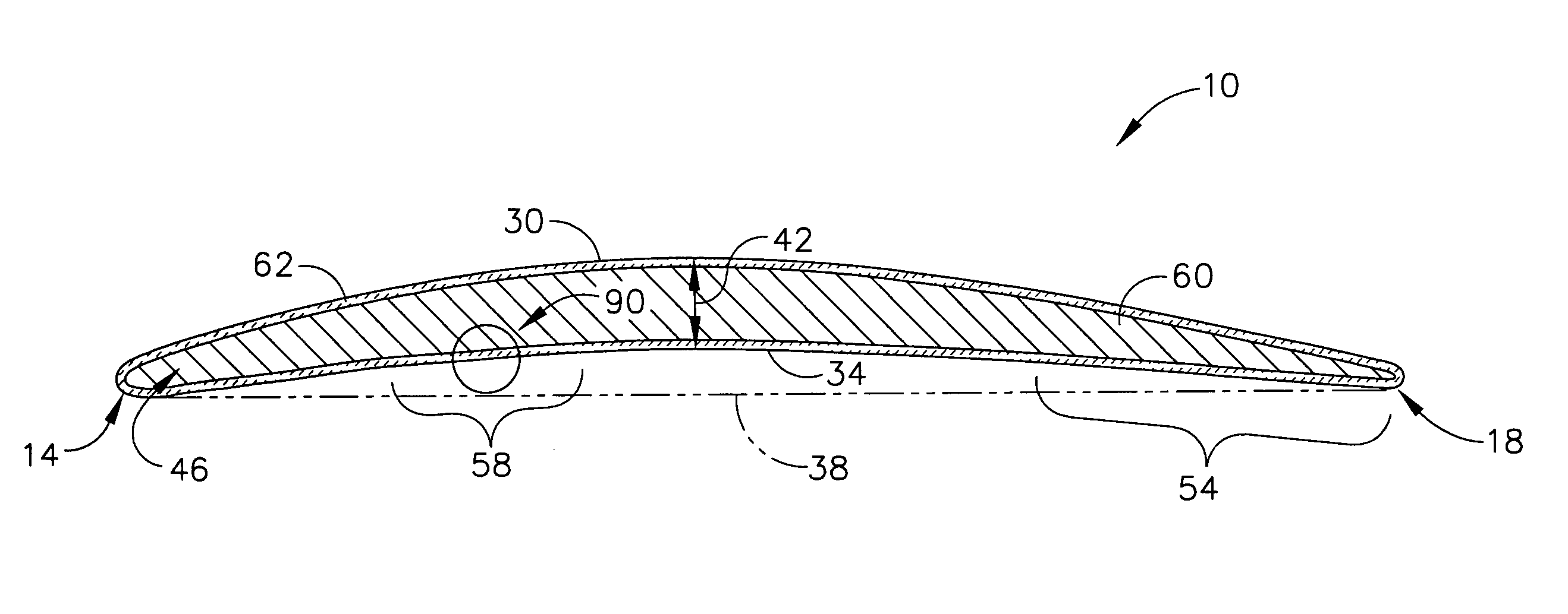
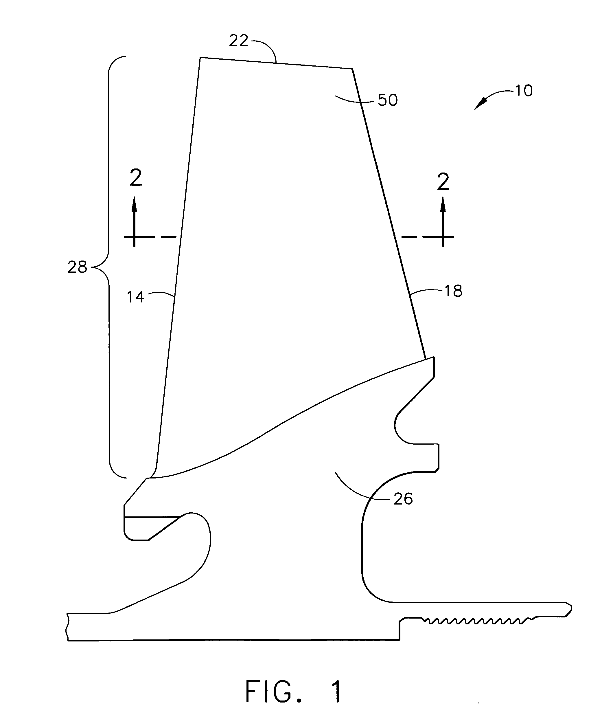
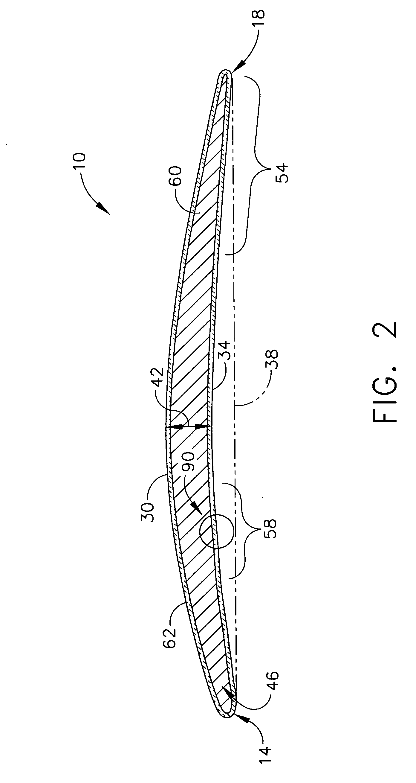
[0009] An embodiment of this invention relates to a turbine airfoil having improved impact resistance, as well as improved erosion resistance. This airfoil has a leading edge, a trailing edge, a convex curved surface suction side extending from the leading to the trailing edge, and a concave curved surface pressure side extending from the leading to the trailing edge, the pressure side having a leading edge portion aft of the leading edge and a trailing edge portion forward of the trailing edge. This airfoil comprises:
[0013] The airfoils of this invention having the improved impact resistant leading edge section and erosion resistant coating, as well as the method of this invention for forming the erosion resistant coating, provide several benefits and advantages. The impact resistant leading edge section improves the impact resistance properties of turbine airfoils, in particular turbine compressor airfoils used in helicopter turboshaft engines. The erosion resistant coating improves the erosion resistance of such airfoils, but without adversely affecting other desirable properties of the turbine airfoil such as high-cycle fatigue strength.

Problems solved by technology

Airfoils used in gas turbine engines can suffer from erosion and impact caused by particles ingested into the engine, especially in helicopter turboshaft engines.
The effects of such ingestion can result in power loss, increased fuel consumption, increased gas turbine generator temperatures, as well as scrapping of compressor components long before the expected fatigue life limits.
Turbine compressor performance can be degraded because of impact damage to the leading edges of the compressor airfoils, as well as erosion of portions of the side or surface of the airfoil beyond the leading edge.
Erosion and impact damage to airfoils can occur relatively quickly in desert environments due to sand ingestion.
The impact of large sand particles can cause burr formation where the leading edge of the airfoil gets rolled or curled over, thus disturbing the airflow and degrading compressor performance.
Additionally, erosion on the pressure surface or side of the airfoil contributes to early replacement or removal as the effective surface area of the airfoil decreases and the cross section (i.e., thickness) becomes too thin.
However, impact and erosion damage is the result of different problems created by the ingestion of these particles.
Impact damage is primarily caused by high kinetic energy particle impacts on the leading edge of the airfoil.
In addition to disturbing the airflow and degrading compressor efficiency, these burrs constrain the airflow, necessitating the engine to compensate by consuming more fuel for the required power.
These glancing impacts on the concave airfoil surface can cause portions thereof to be eroded.
As a result, the airfoil steadily loses its effective surface area due to significant chord length loss, as well as becoming thinner, resulting in a decrease in compressor performance of the engine.
However, standard titanium nitride coatings are less capable of resisting impact damage caused by particles that strike the leading edge of the airfoil directly or head on.
Titanium nitride coatings can also adversely impact the high-cycle fatigue (HCF) strength of the airfoil.
However, such tungsten carbide coatings are often too thick and heavy to be applied to fast rotating airfoils, especially for helicopter turboshaft engines, and are generally too thick to be implemented with existing airfoil designs.

Method used


Image

  • Airfoil having improved impact and erosion resistance and method for preparing same
  • Airfoil having improved impact and erosion resistance and method for preparing same
  • Airfoil having improved impact and erosion resistance and method for preparing same

Examples


Embodiment Construction

[0020] As used herein, the term “elongation” refers to the increase in gage length of the specimen measured after fracture of the specimen within the gage length, and expressed as the percentage of the original gage length or “elongation percentage” (Ep) according to the following equation:

Ep=[(Lx−Lo) / Lo]×100

[0021] wherein Lo is the original gage length and Lx is the final gage length. See Davis, ASM Materials Engineering Dictionary (1992), p. 114

[0022] As used herein, the term “fracture toughness” refers to the measurement of the resistance of the specimen being tested to extension of a crack. Fracture toughness of a specimen is measured herein by the Charpy impact test. See Davis, ASM Materials Engineering Dictionary (1992), p. 72.

[0023] As used herein, the term “hardness” refers to the measurement of the resistance of the material to surface indentation or abrasion. The hardness of a material is measured herein by units of indentation (in GPa) using Brinell or Rockwell hardne...


PUM

PropertyMeasurementUnit
Fractionaaaaaaaaaa
Pressureaaaaaaaaaa
Pressureaaaaaaaaaa

Abstract

A turbine airfoil having an improved impact and erosion resistance. The airfoil comprises: (a) a base segment having an impact resistant leading edge section proximate to the leading edge comprising a material having having a yield strength of least about 250 ksi and an elongation percentage of about 12% or less; and (b) an erosion resistant coating overlaying the base segment at least in the leading and trailing edge portions of the pressure side, the erosion resistant coating comprising at least one ceramic layer having at least one of the following properties: (1) an erosion value of at least about 200 g. of erodent to cause a thickness loss of about 15-20 microns; (2) an erosion volume loss value (V) of about 1.9 or less as defined by the equation V=H−0.18×E0.75×F−1.65 where H is hardness, E is elastic modulus and F is fracture toughness; and (3) an F value of at least about 1.5 MPa*m1 / 2. The erosion resistant coating can comprise alternating ceramic and metallic layers and is typically formed by a method involving the step of forming on the pressure side of the base segment of the airfoil in alternating fashion at least one ceramic layer and at least one metallic layer.

Description

STATEMENT REGARDING FEDERALLY SPONSORED RESEARCH [0001] This invention was made with Government support under Contract No. N00019-96-C-0176 awarded by the Office of Naval Research. The Government may have certain rights to the invention.BACKGROUND OF THE INVENTION [0002] This invention relates to turbine airfoils, especially turbine compressor airfoils, having improved impact and erosion resistance. This invention further relates to a method for forming improved erosion resistance coatings on these turbine airfoils. [0003] Airfoils used in gas turbine engines can suffer from erosion and impact caused by particles ingested into the engine, especially in helicopter turboshaft engines. This is particularly true of the airfoils that comprise the turbine engine compressors. The effects of such ingestion can result in power loss, increased fuel consumption, increased gas turbine generator temperatures, as well as scrapping of compressor components long before the expected fatigue life lim...

Claims


Application Information

Patent Timeline
IPC IPC(8): B63H1/26
CPCC23C30/00F01D5/288F01D25/007Y02T50/672F05D2230/90Y10T428/12458C23C28/321C23C28/322C23C28/34C23C28/341C23C28/42F05D2260/95F04D29/324F05D2240/303F04D29/023Y02T50/60
Inventor BRUCE, ROBERT WILLIAMSCHELL, JERRY DONALDGORMAN, MARK DANIEL
Owner GENERAL ELECTRIC CO
Why Eureka
Try Eureka