
Plasma reactor and plasma reaction apparatus

a plasma reactor and plasma technology, applied in the field of plasma reactors, can solve the problems of high heat resistance and the need to use a large amount of precious metal catalysts, and achieve the effects of reducing size, increasing heat transfer properties, and heat retaining properties

Inactive Publication Date: 2009-08-20
NGK INSULATORS LTD
View PDF6 Cites 4 Cited by
  • Summary
  • Abstract
  • Description
  • Claims
  • Application Information

AI Technical Summary

Benefits of technology

The present invention provides a plasma reactor that can efficiently produce gas by utilizing plasma, catalysts, and a heat-supplying gas circulation section. The integrated structure of the plasma reaction section and the heat-supplying gas circulation section allows for the efficient production of gas. The plasma reactor can use a large amount of precious metal catalysts, which are expensive, by heating the catalyst with the second gas that passes through the plasma reaction section. The plasma reactor can also use a plasma generation surface with a ceramic dielectric and a conductor buried in the ceramic dielectric to support the catalyst. The plasma reactor can be stacked integrally with the heat-supplying gas circulation section. The plasma reactor can efficiently produce gas by circulating the first gas through the plasma reaction section and applying heat to the second gas in the heat-supplying gas circulation section. The plasma reactor can also use a gas introduction / circulation section and through-holes to efficiently introduce and circulate the first gas.

Problems solved by technology

The catalyst quickly deteriorates when the processing target gas is heated to such a high temperature.
This makes it necessary to use a large amount of expensive precious metal catalyst having high heat resistance.

Method used


Image

  • Plasma reactor and plasma reaction apparatus
  • Plasma reactor and plasma reaction apparatus
  • Plasma reactor and plasma reaction apparatus

Examples


second embodiment

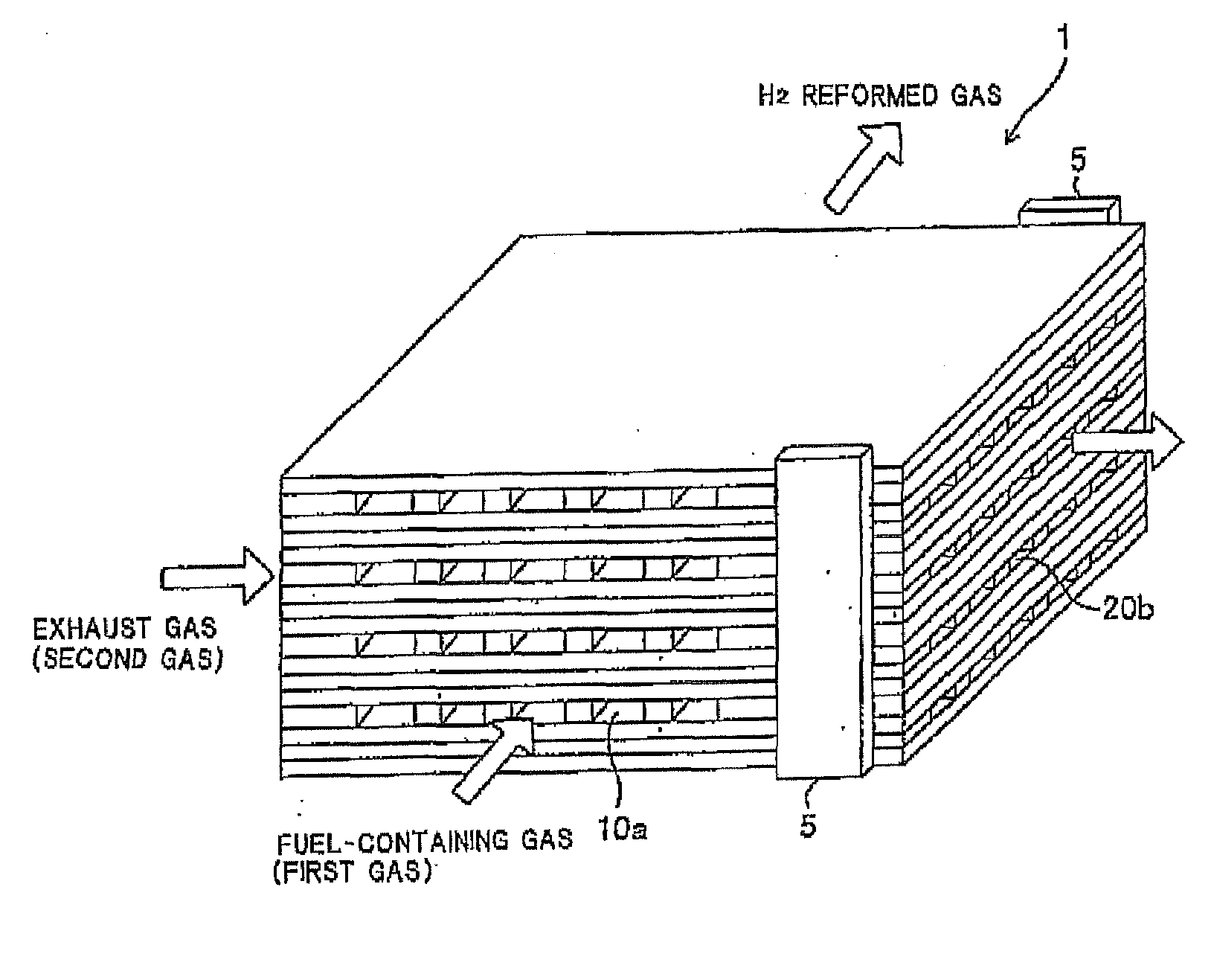
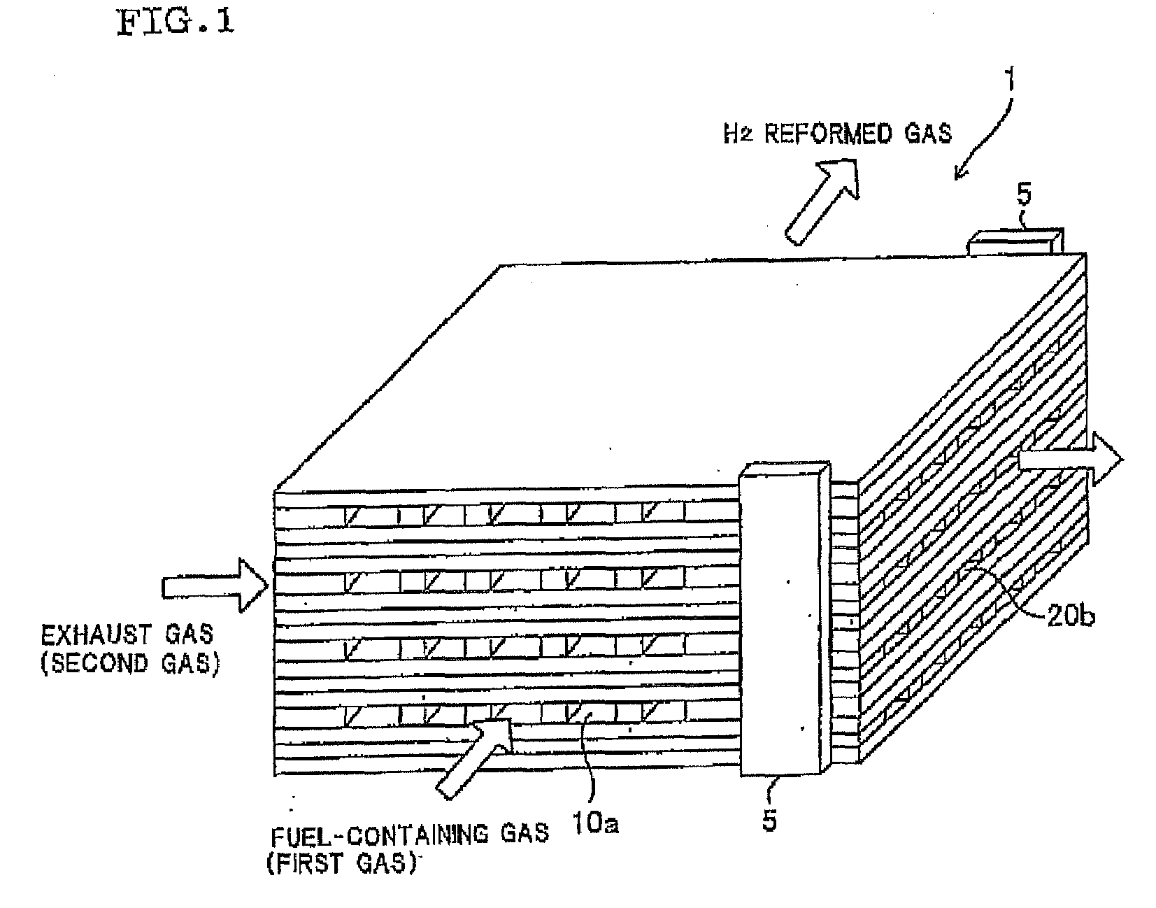
[0059]A plasma reactor 1 according to a second embodiment is described below with reference to FIGS. 5 and 6. The plasma reaction section 10 and the heat-supplying gas circulation section 20 are integrally stacked in the same manner as in the first embodiment. The first gas circulation direction and the second gas circulation direction are crossed to the stacking direction, and the first gas circulation path and the second gas circulation path are formed so that the first gas circulation direction is crossed to the second gas circulation directions.

[0060]In the second embodiment, the gas inlet 10a and the gas outlet 10b of the plasma reaction section 10 are formed on one end face of the plasma reaction section 10 in the direction crossed to the stacking direction. The terminals 5 connected to the pulse power supply 31 are formed on the end face opposite to the end face on which the gas inlet 10a and the gas outlet 10b of the plasma reaction section 10 are formed in order to apply a ...

example 1

(1) Production of Alumina Tabular Electrode

Basic Electrode

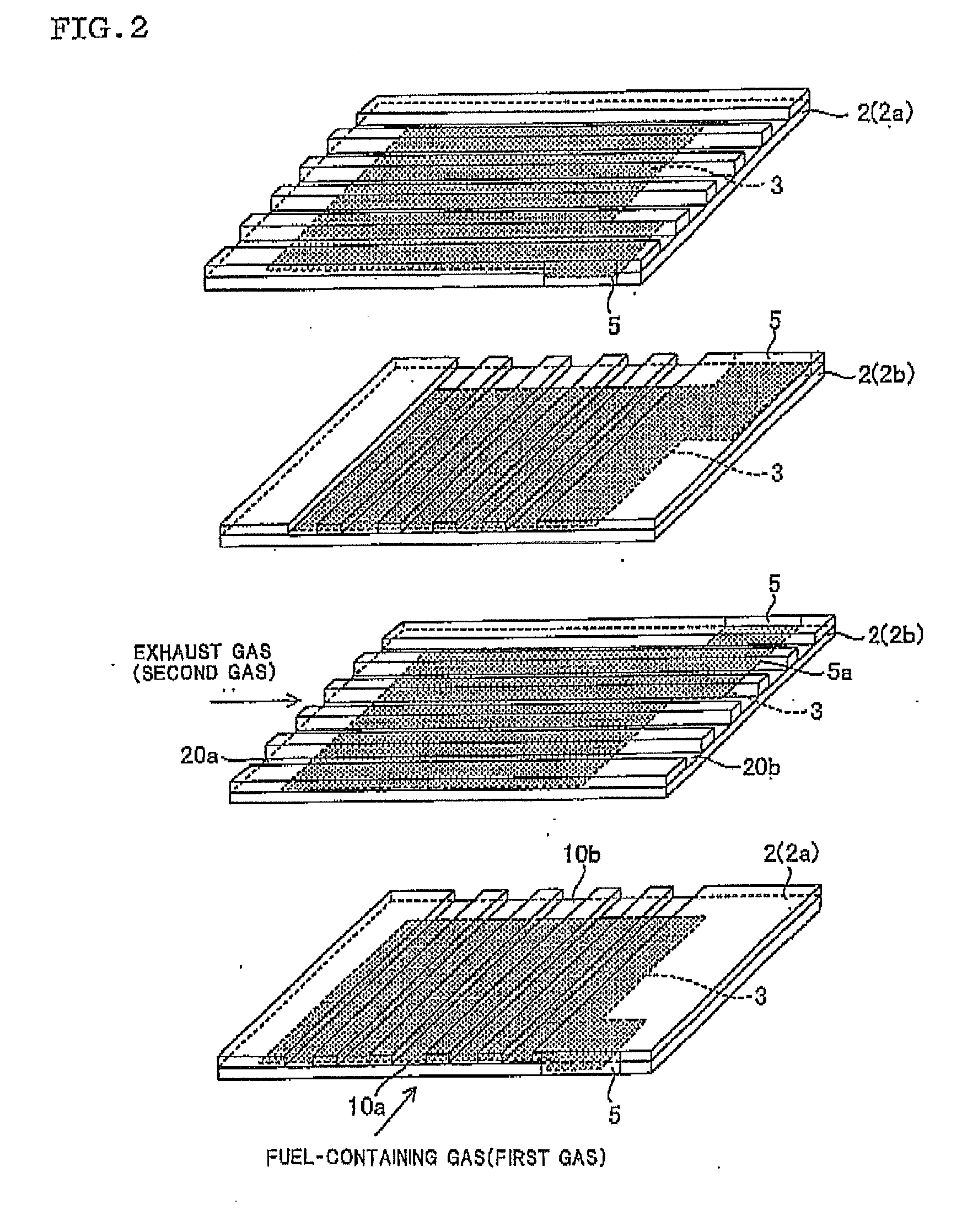
[0071]A forming aid, a plasticizer, and the like were added to a 93% alumina (Al2O3) raw material to prepare an alumina tape (thickness after firing: 0.25 mm). An alumina tabular plate (basic electrode) having a width of 50 mm and a length of 60 mm was prepared using the resulting tape. A conductor film (conductor 3) having a width of 48 mm, a length of 45 mm, and a thickness of 10 μm was printed on the alumina tabular plate using a tungsten paste to obtain an integrally stacked tabular electrode. A pull-out section 5a connected to the terminal 5 was also printed (see FIG. 2). The same tape material as the alumina tape on which the conductor film was printed was then press-bonded with heating to obtain an alumina tabular electrode (tabular electrode 2) having a thickness of 0.5 mm.

(2) Production of Cross-Flow Heat Exchanger-Integrated Through-Flow Reactor

First Embodiment

[0072]A support section 7 was formed by stacking four al...

example 2

Production of Cross-Flow Heat Exchanger-Integrated Catalyst-Supporting Through-Flow Reactor

First Embodiment

[0073]An alumina fine powder (specific surface area: 107 m2 / g) was impregnated with a nickel nitrate (Ni(NO3)2) aqueous solution, dried at 120° C., and fired at 550° C. for three hours in air to obtain an Ni / alumina powder containing nickel (Ni) in an amount of 20 mass % based on alumina. After the addition of alumina sol and water to the Ni / alumina powder, the pH of the mixture was adjusted to 4.0 using a nitric acid solution to obtain a slurry. The reactor was immersed in the slurry, dried at 120° C., and fired at 550° C. for one hour in a nitrogen atmosphere to obtain a cross-flow heat exchanger-integrated catalyst-supporting through-flow reactor shown in FIGS. 1 to 3. The amount of Ni supported on the reactor was 30 g / l.


PUM

PropertyMeasurementUnit
particle diameteraaaaaaaaaa

Abstract

A plasma reactor includes a plasma reaction section that includes a pair of tabular electrodes facing each other arranged with an opening and generates plasma in a discharge section between the pair of tabular electrodes upon application of a voltage between the pair of tabular electrodes so that a first gas that passes through the discharge section is made to undergo a reaction, each of the pair of tabular electrodes including a ceramic dielectric and a conductor buried in the ceramic dielectric, and a heat-supplying gas circulation section that is stacked adjacently to the plasma reaction section and is integrally formed with the plasma reaction section, the heat-supplying gas circulation section applying heat of a second gas that passes through to the plasma reaction section to promote the reaction of the first gas.

Description

BACKGROUND OF THE INVENTION[0001]1. Field of the Invention[0002]The present invention relates to an integrated plasma reactor that includes a plasma reaction section and a heat-supplying gas circulation section, the plasma reaction section allowing gas introduced between a pair of tabular electrodes to undergo a reaction by generating plasma, and a plasma reaction apparatus.[0003]2. Description of Related Art[0004]A silent discharge occurs when disposing a dielectric between a pair of tabular electrodes and applying a high alternating-current voltage or a periodic pulse voltage between the electrodes. Active species, radicals, and ions are produced in the resulting plasma field to promote a reaction and decomposition of gas. This phenomenon may be utilized to remove toxic components contained in engine exhaust gas or incinerator exhaust gas.[0005]Technology that mixes hydrocarbon fuel and air, reforms the mixture using a catalyst, and supplies a reformed gas containing hydrogen to a...

Claims


Application Information

Patent Timeline
Patent Type & Authority Applications(United States)
IPC IPC(8): B01J19/08
CPCH05H1/24H05H1/2406H05H1/2437H05H1/2418H05H2245/17H01J37/34B01J19/088
Inventor MASUDA, MASAAKITAKAHASHI, MICHIOMIZUNO, HIROSHI
Owner NGK INSULATORS LTD
Learn More