In-situ diffusion alloying and pre-oxidation annealing in air of fe-cr-al alloy catalytic converter material

Inactive Publication Date: 2009-04-23
EMS ENGINEERED MATERIALS SOLUTIONS LLC
View PDF6 Cites 1 Cited by
  • Summary
  • Abstract
  • Description
  • Claims
  • Application Information

AI Technical Summary

Benefits of technology

[0009]Accordingly, the present invention provides for a method to manufacture ferritic metal foil, such as that made from roll-bonding and typically utilized in catalytic converters, with high oxidation resistance and dimension stability at high temperatures in an exhaust gas atmosphere. Further, a pre-oxidized surface film containing Al oxides is produced which has good adhesion upon being subject to catalytic wash coating. In addition, the final material is easily and economically manufactured for high volume applications.
[0013]The resulting converters are a finished product having aluminum in the multilayer composite material which has already diffused into the Fe—Cr to form a monolithic FeCrAl alloy with pre-oxidized foil surfaces. That is the in-situ diffusion alloying and pre-oxidation in the material of the catalytic converter are obtained in a single process after a honeycomb-like catalytic converter is made. Since the thermal treatment is needed during catalytic converter manufacturing, the method of the invention provides a cost effective process in the manufacture of catalytic converters. As a result of the novel process of the present invention, the material used in the catalytic converters has improved dimensional stability with proper surface morphology for good catalysis washing coating adhesion.

Problems solved by technology

Moreover, halogen compounds (e.g. salt) employed for preventing freezing during cold seasons are liable to enter these components of ferrous base alloy material, which are then corroded by the atmosphere containing halogen gas produced when the halogen compounds are decomposed at high temperatures.
These FeCrAl alloys, however, are difficult to produce by conventional rolling and annealing processes.
To overcome the processing difficulties, it has been suggested, as in EP application 91115501.8, to produce the foil by a rapid solidification processing method; but such processing is expensive and requires very precise controls.
However, in all of these applications the control of the processing parameters is complex and expensive.
Further the final foil has not proven, in many cases, to have the desired corrosion / oxidation resistance at elevated temperatures required in the catalytic converter industry.
Further the oxidation resistance and dimension stability for such materials has not been reported.
Still, no data of oxidation resistance and dimension stability performance were reported.

Method used


Image

  • In-situ diffusion alloying and pre-oxidation annealing in air of fe-cr-al alloy catalytic converter material
  • In-situ diffusion alloying and pre-oxidation annealing in air of fe-cr-al alloy catalytic converter material
  • In-situ diffusion alloying and pre-oxidation annealing in air of fe-cr-al alloy catalytic converter material

Examples


example iii

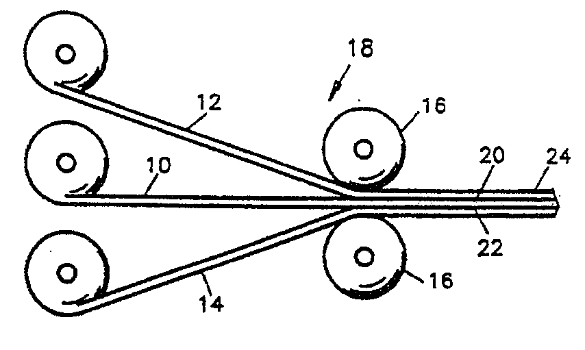
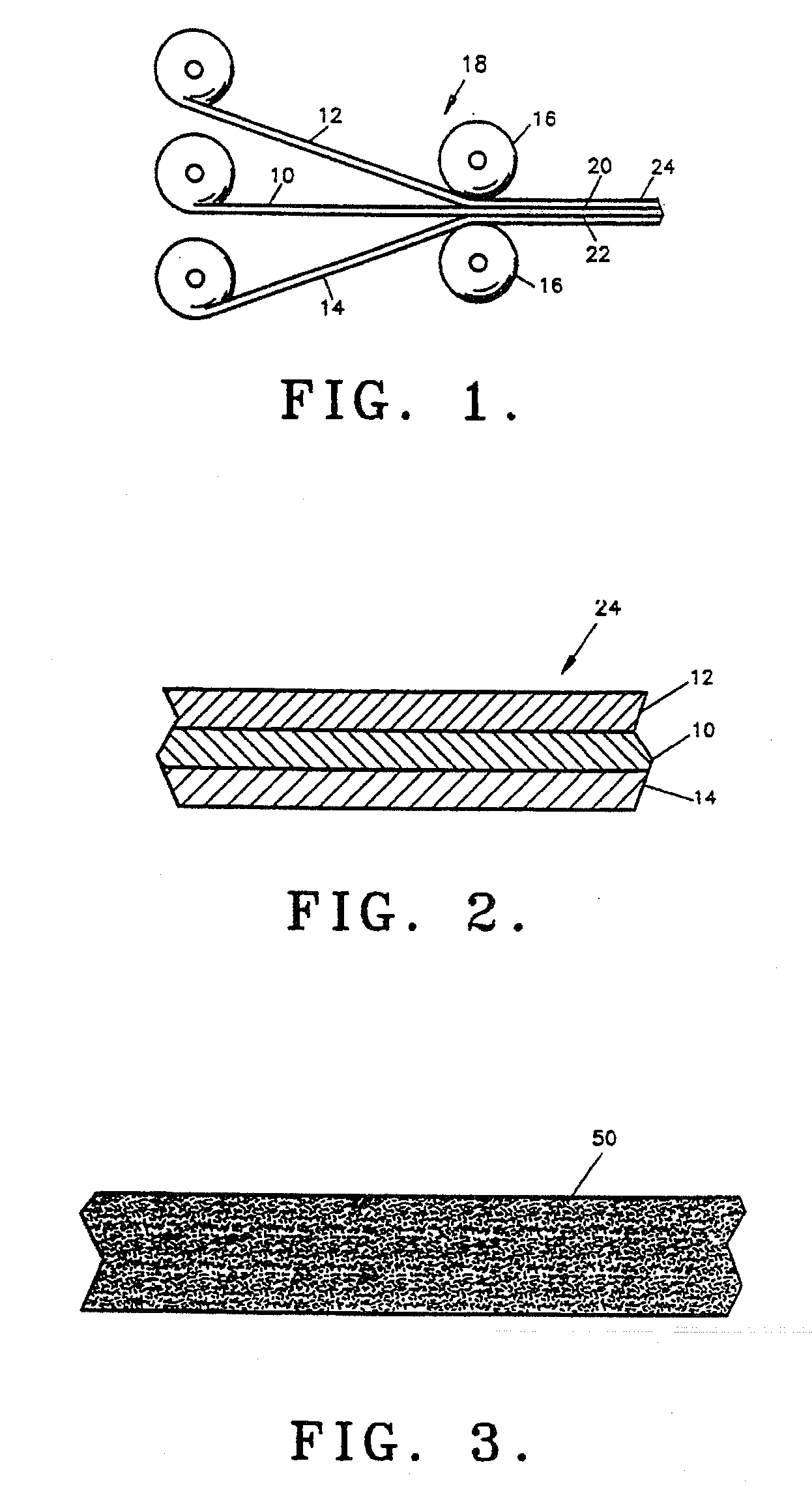
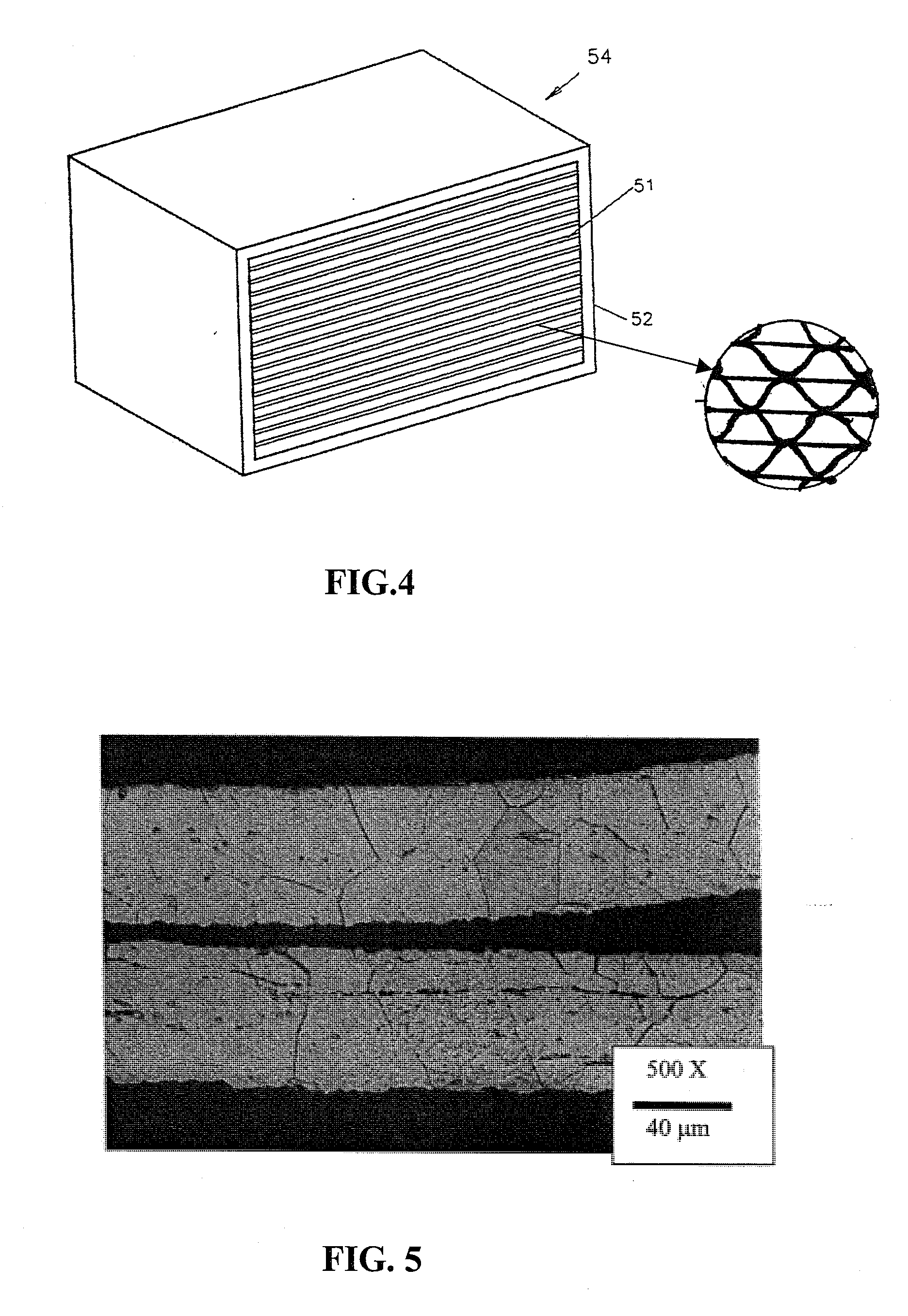
[0061]This example was carried out identical to Example I except that the heat treatment was performed differently. The honeycomb-like converter samples were made from the foil composite material at a thickness of about 0.002 inches, as described in Example I. These honeycomb-like samples were placed directly into a furnace which was already at a holding temperature of between about 900° C. to about 1150° C., which was well above the aluminum melting point and at alpha alumina formation temperature range, holding for different times from about 10 minutes to about 120 minutes, and then cooled down with the furnace. The heat treatments were performed in the atmosphere of air instead of in vacuum condition. The details of the different heat treatment schedules is listed in Table 4 below. After the heat treatments, the composite material foil in the honeycomb-like converter samples became homogenous as showed in FIG. 5, while an alumina film was formed on the surfaces of the material as...

example iv

[0064]This example was carried out identical to Example III except the heat treatment schedule was different. The honeycomb-like catalytic converter roll samples were placed into a conventional heat treating electric furnace which had already reached a temperature of about 720° C. and was then heated to a temperature of about 980° C. within approximately 30 minutes and held for about 2 hours followed by furnace cooling. The treated converter samples were then coated by catalysis wash coating. The special tests showed that the adhesion between catalysis wash coating and pre-oxide surfaces of materials in the catalytic converter samples were strong and acceptable from the industrial standard.

[0065]The novel process and article produced by method of the present invention provides for a foil material which can be used in catalytic converters, wherein the foil material exhibits improved corrosion resistance at elevated temperatures, improved thermal dimension stability, and excellent sur...


PUM

PropertyMeasurementUnit
Temperatureaaaaaaaaaa
Timeaaaaaaaaaa

Abstract

A manufacturing method of metal substrate catalytic converter and the resulting product. In this method, a multiple layer aluminum and ferritic stainless steel composite material is first made by roll-bonding and then further processed to a final foil thickness. The composite foils are then fabricated to a honeycomb-like converter with air flow channels. The converter is then thermally treated at a high temperature during a necessary converter fabrication process. The monolithic FeCrAl alloy is then obtained in the converter by in-situ diffusion alloying with pre-oxide film on the surfaces. The resulted material has improved oxidation resistance and thermal dimension stability at a high temperature.

Description

RELATED APPLICATIONS[0001]This application is based upon and claims the benefit of priority from U.S. application Ser. No. 10 / 807,792 filed on Mar. 24, 2004, which is based upon and claims the benefit of priority from U.S. Provisional Application No. 60 / 493,168 filed on Aug. 7, 2003, and U.S. Provisional Application No. 60 / 457,079 filed on Mar. 24, 2003, the contents of which are all expressly incorporated herein by reference.TECHNICAL FIELD[0002]This present invention is directed to a product and method of producing the product wherein the product is useful in the production of catalytic converters. More specifically, this application relates to in-situ diffusion alloying and pre-oxidation annealing, in air, of an FeCrAl alloy which is particularly useful in catalytic converters.BACKGROUND OF THE INVENTION[0003]This invention provides a method for the manufacturing of a metallic catalytic converter material having corrosion resistance and thermal dimension stability at high tempera...

Claims


Application Information

Patent Timeline
IPC IPC(8): B01D53/34B21D51/16B32B3/12B01J35/04B01J37/08B23K20/04B23K20/227
CPCB01J35/04B01J37/08B23K20/04B23K20/2275B23K2201/02Y10T428/24149C22C38/02C22C38/04C22C38/06Y10T29/49345Y10T428/1234B32B15/012B23K2101/02B01J35/56
Inventor CHEN, LICHUN LEIGHJHA, BIJENDRA
Owner EMS ENGINEERED MATERIALS SOLUTIONS LLC
Why Eureka
Try Eureka