Charge trapping memory cell with high speed erase

a memory cell and high-speed erase technology, applied in the field of flash memory technology, can solve the problems of limiting the ability to increase the density of flash memory, affecting the performance of flash memory, so as to achieve high speed, eliminate the hole tunneling barrier, and effectively prevent the effect of charge leakag

Inactive Publication Date: 2009-02-12
MACRONIX INT CO LTD
View PDF82 Cites 94 Cited by
  • Summary
  • Abstract
  • Description
  • Claims
  • Application Information

AI Technical Summary

Benefits of technology

[0011]The valence band energy level at the first offset is such that an electric field sufficient to induce hole tunneling through the thin region between the interface with the semiconductor body and the offset, is also sufficient to raise the valence band energy level after the offset to a level that effectively eliminates the hole tunneling barrier in the engineered tunneling dielectric after the offset. This structure enables electric field assisted hole tunneling at high speeds while effectively preventing charge leakage through the engineered tunneling dielectric in the absence of electric fields or in the presence of smaller electric fields induced for the purpose of other operations, such as reading data from the cell or programming adjacent cells.
[0012]In a representative device, the engineered tunneling dielectric layer consists of an ultrathin silicon oxide layer O1 (e.g. <=15 Å), an ultrathin silicon nitride layer N1 (e.g. <=30 Å) and an ultrathin silicon oxide layer O2 (e.g. <=30 Å), which results in an increase in the valence band energy level of about 2.6 eV at an offset 15 Å or less, from the interface with the semiconductor body. The O2 layer separates the N1 layer from the charge trapping layer, at a second offset (e.g. about 35 to 45 A from the interface), by a region of lower valence band energy level (higher hole tunneling barrier). The electric field sufficient to induce hole tunneling between the interface and the first offset also raises the valence band energy level after the second offset to a level that effectively eliminates the hole tunneling barrier, because the second offset is at a greater distance from the interface. Therefore, the O2 layer does not significantly interfere with the electric field assisted hole tunneling, while improving the ability of the engineered tunneling dielectric to block leakage during low fields.
[0014]The present technology combines techniques for reducing the electric field in the blocking dielectric layer relative to the tunneling dielectric layer, with techniques for reducing the magnitude of the electric field required for erase to achieve high speed erase operations without saturation, enabling a large memory window compared to prior devices. Also, charge retention and endurance characteristics of the memory cell are very good.
[0017]In the technology described herein, the bias voltages across the gate and substrate of the device are 20 V or less, well below breakdown voltages for erase operations, and demonstrate threshold shifts supporting a memory window of as much as 7 V or more. In addition, for the device described herein, the bias voltages applied during erase operations induce an electric field less than 14 MV / cm across the dielectric tunneling layer, and accomplish a threshold shift of greater than 5 V in less than 10 ms, without erase saturation. Circuitry can be implemented in combination with the charge trapping memory cell described herein to accomplish a negative threshold shift of greater than 5 V in less than 1 ms without erase saturation. Erase speeds of less than 10 ms can be accomplished using bias voltages less than 15 V, enabling the implementation of very small scale devices that have relatively low breakdown voltages.
[0019]The memory cell described herein can provide flash technology with a relatively large memory window (greater than 7 V) with excellent data retention. Also, the memory cell described herein should be scalable to 50 nm manufacturing nodes, to 40 nm nodes and below.

Problems solved by technology

As the density increases in memory devices, and the floating gate memory cells get closer and closer together, interference between the charge stored in adjacent floating gates becomes a problem.
This is limiting the ability to increase the density of flash memory based on floating gate memory cells.
However at that thickness, the endurance and charge retention characteristics of the memory cell are poor relative to traditional floating gate technology.
Also, with relatively thick tunneling dielectric layers, the electric field required for the erase operation also cause electron injection from the gate through the blocking dielectric layer.
However, if the erase saturation level is too high, the cell cannot be erased at all, or the threshold margin between the programmed and erased states becomes too small for many applications.
Decreasing the thickness of the tunneling dielectric layer is limited by issues of charge retention and erase saturation, as mentioned above.
However, the problem of the erase saturation continues to limit operational parameters of the device.

Method used


Image

  • Charge trapping memory cell with high speed erase
  • Charge trapping memory cell with high speed erase
  • Charge trapping memory cell with high speed erase

Examples


Embodiment Construction

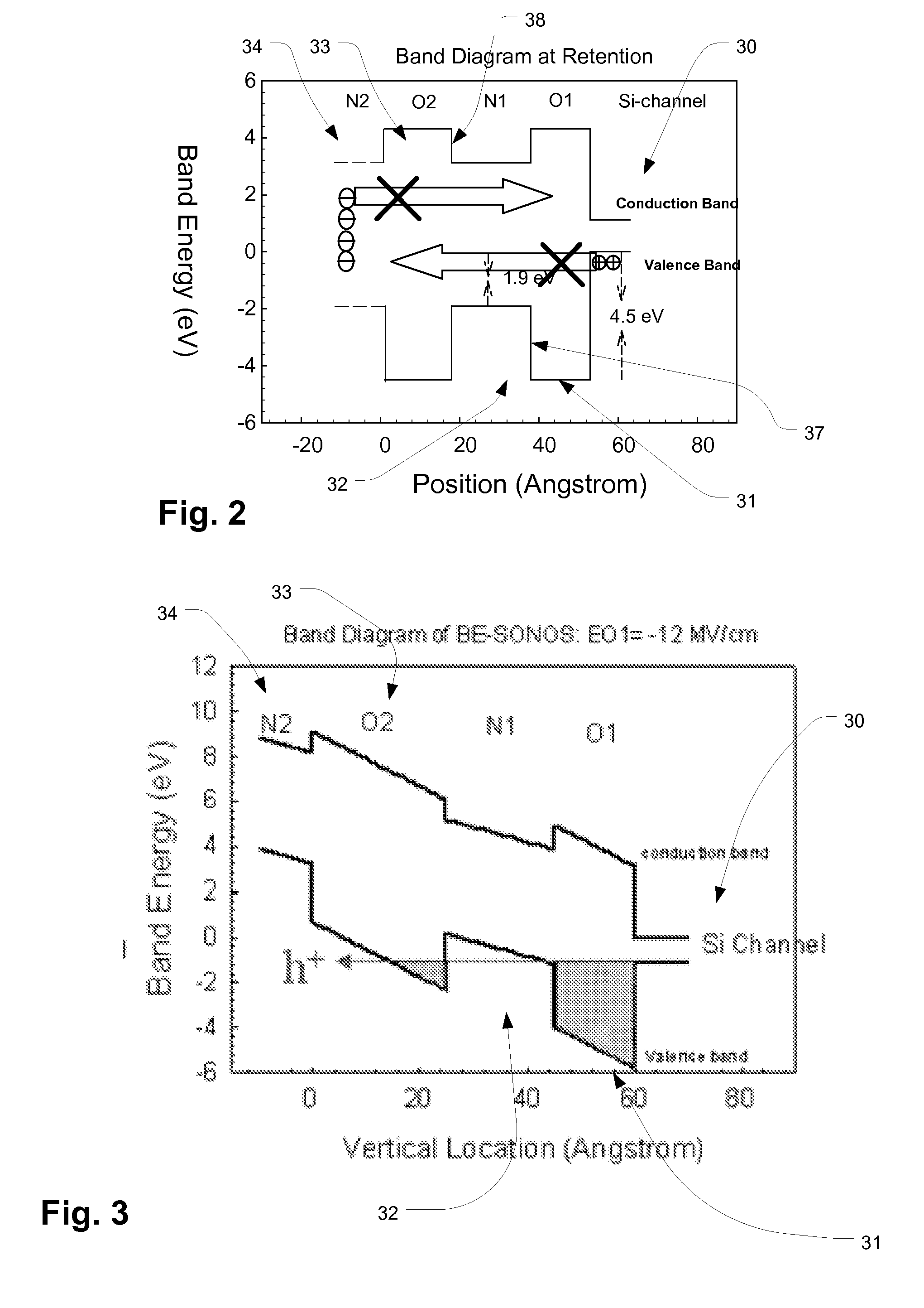
[0036]A detailed description of embodiments of the present invention is provided with reference to the FIGS. 1-15.

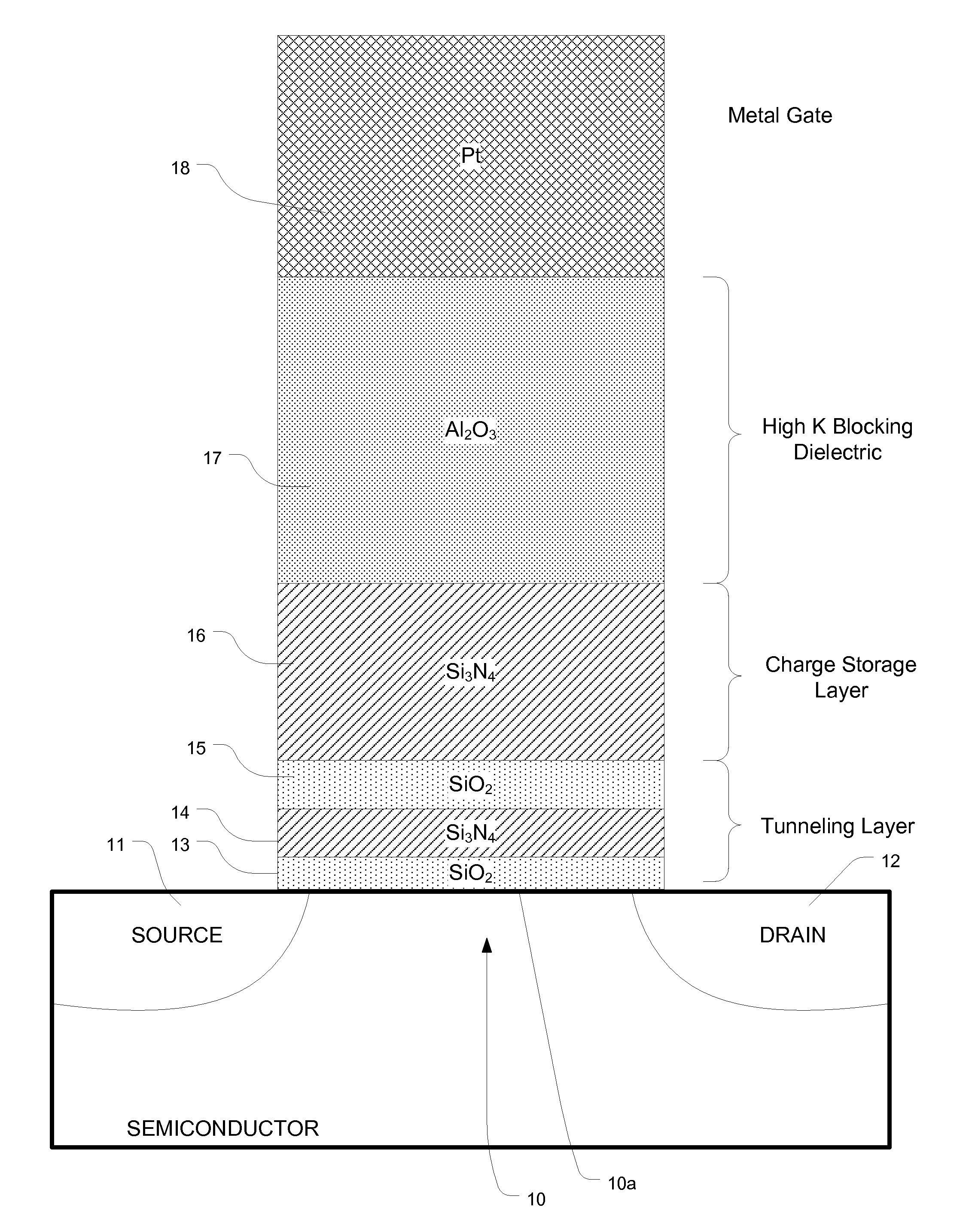
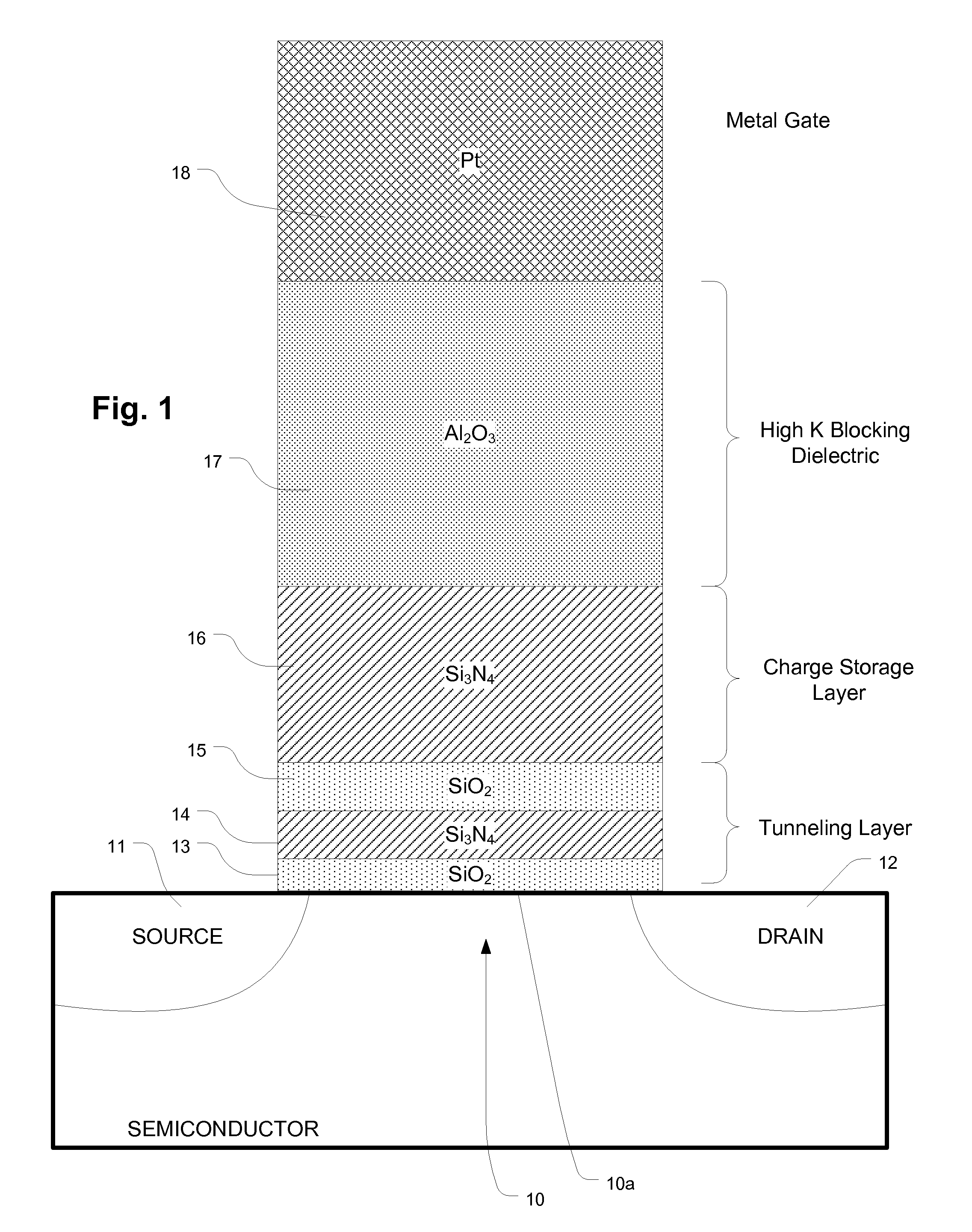
[0037]FIG. 1 is a simplified diagram of a charge trapping memory cell employing a high κ blocking dielectric layer and a band gap engineered dielectric tunneling layer. The memory cell includes a channel 10 in a semiconductor body, and a source 11 and a drain 12 adjacent channel.

[0038]A gate 18 in this embodiment comprises platinum having a work function of about 8 electron volts eV. Preferred embodiments employ metals or metal compounds for the gate 18, such as platinum, tantalum nitride, aluminum or other metal or metal compound gate materials. It is preferable to use materials having work functions higher than 4.5 eV. A variety of high work function materials suitable for use as a gate terminal are described in U.S. Pat. No. 6,912,163, referred to above. Such materials are typically deposited using sputtering and physical vapor deposition technologies, and can be patt...


PUM


Abstract

A band gap engineered, charge trapping memory cell includes a charge trapping element that is separated from a metal or metal compound gate, such as a platinum gate, by a blocking layer of material having a high dielectric constant, such as aluminum oxide, and separated from the semiconductor body including the channel by an engineered tunneling dielectric. Fast program and erase speeds with memory window as great as 7 V are achieved.

Description

CROSS REFERENCE TO RELATED APPLICATION[0001]The benefit of U.S. Provisional Patent Application No. 60 / 955,391, filed on 13 Aug. 2007, is hereby claimed.BACKGROUND OF THE INVENTION[0002]1. Field of the Invention[0003]The present invention relates to flash memory technology, and more particularly to scalable charge trapping memory technology adaptable for high speed erase and program operations.[0004]2. Description of Related Art[0005]Flash memory is a class of non-volatile integrated circuit memory technology. Traditional flash memory employs floating gate memory cells. As the density increases in memory devices, and the floating gate memory cells get closer and closer together, interference between the charge stored in adjacent floating gates becomes a problem. This is limiting the ability to increase the density of flash memory based on floating gate memory cells. Another type of memory cell used for flash memory can be referred to as a charge trapping memory cell, which uses a die...

Claims


Application Information

Patent Timeline
Patent Type & Authority Applications(United States)
IPC IPC(8): H01L29/792H10B69/00
CPCG11C16/0466G11C16/0483H01L21/28282H01L29/792H01L27/11568H01L29/513H01L27/115H01L29/40117H10B43/30H10B69/00
Inventor LUE, HANG TINGLAI, SHENG-CHIH
Owner MACRONIX INT CO LTD
Why Eureka
Try Eureka