
Method of cleaning fouled or scaled membranes

a reverse osmosis and membrane cleaning technology, applied in the direction of filtration separation, hollow article cleaning, separation processes, etc., can solve the problems of accelerating the rate, prone to fouling in membrane separation processes, and particularly detrimental to membrane separation systems

Active Publication Date: 2008-07-17
DISCUS DENTAL LLC +1
View PDF5 Cites 30 Cited by
  • Summary
  • Abstract
  • Description
  • Claims
  • Application Information

AI Technical Summary

Benefits of technology

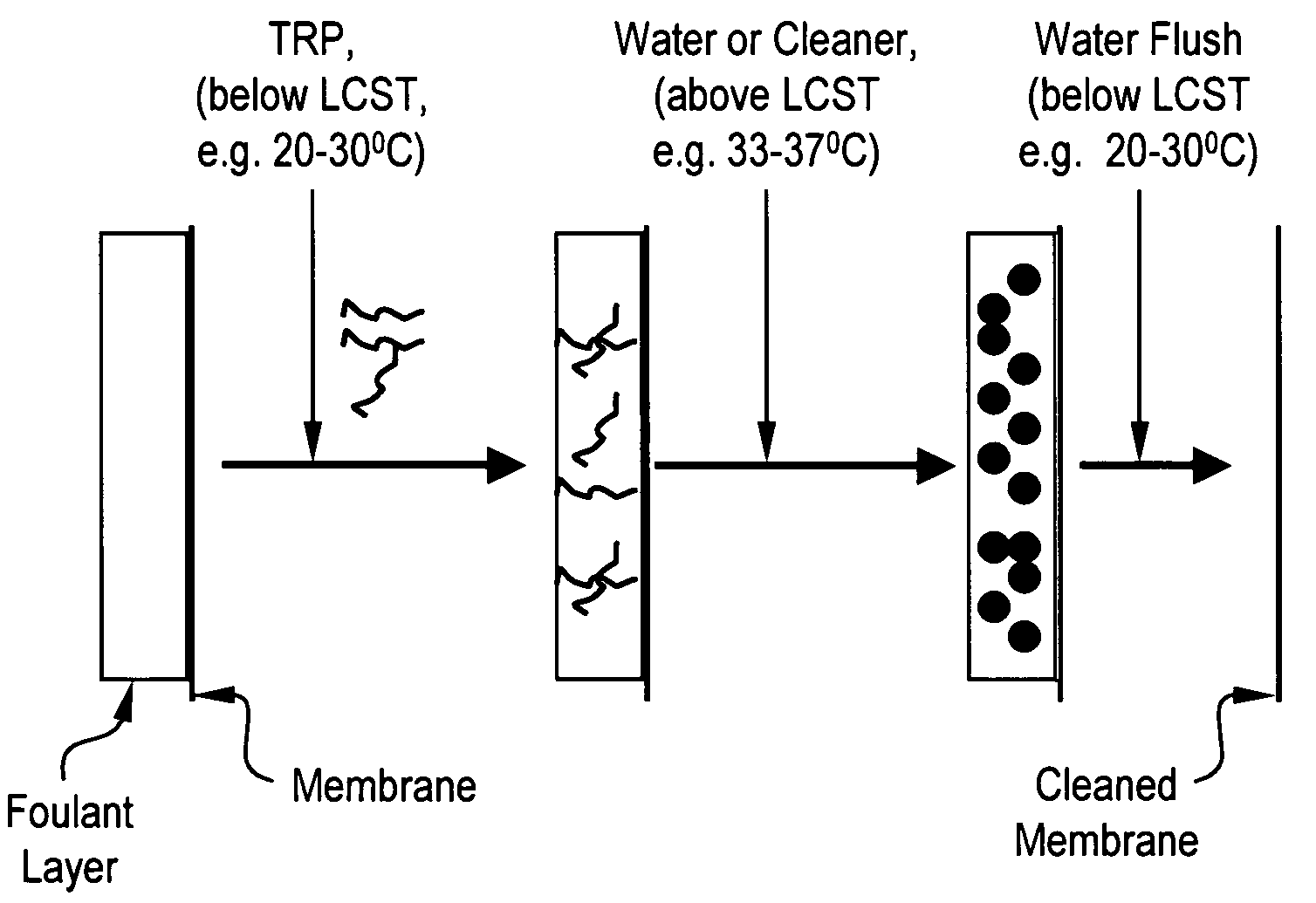
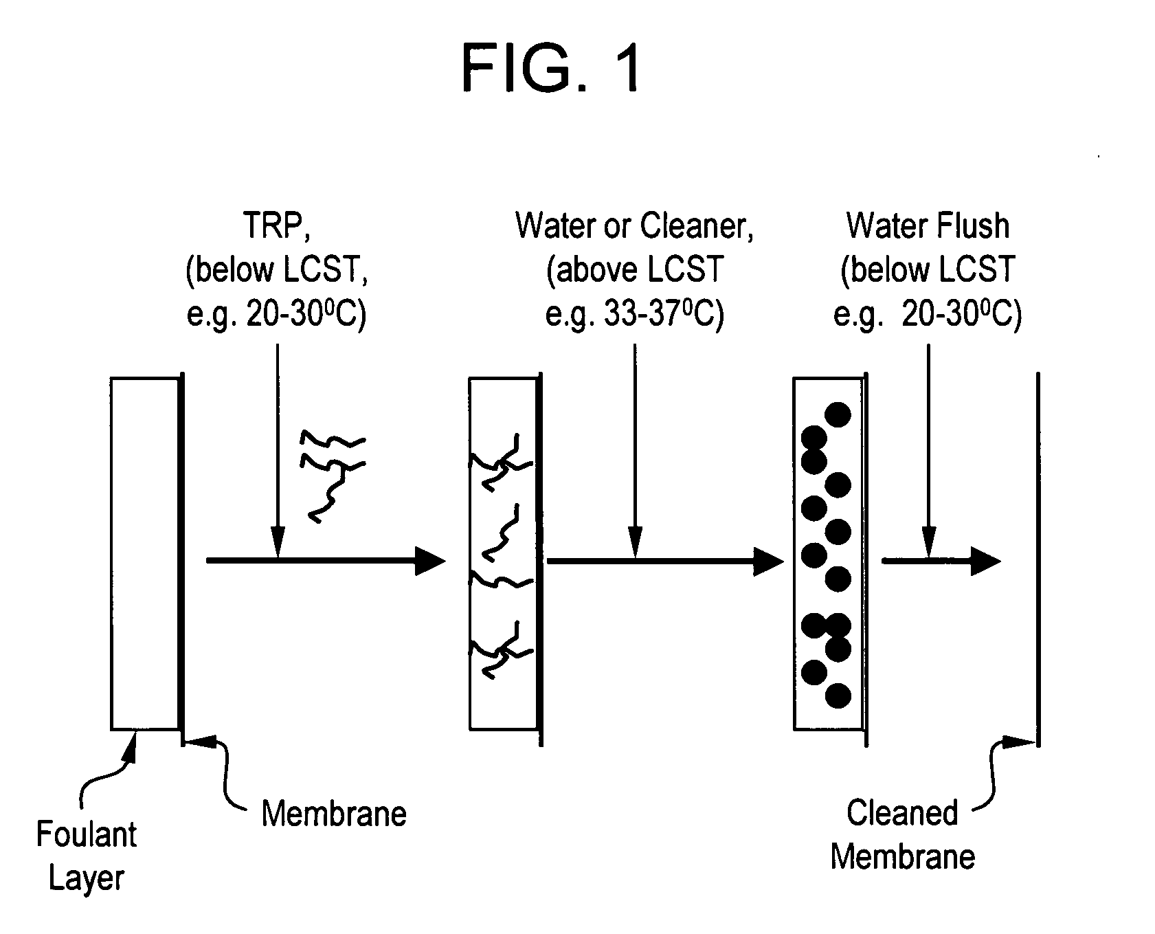
[0010]The present disclosure provides for method of cleaning a fouled or a scaled RO or NF membrane surface in a membrane separation system comprising: treating the membrane surface in a membrane separation system with a solution containing one or more TRP, wherein said TRP is soluble in said solution and at least an effective amount of said TRP diffuses into a foulant layer on said membrane surface; making insoluble said TRP diffused into said foulant layer; and optionally, rinsing the membrane.

Problems solved by technology

Membrane separation processes are prone to fouling by microbes, i.e. biofouling, particularly in aqueous streams, which provide optimum conditions for microbial growth.
Biofouling is particularly detrimental to membrane separation systems because once it is started, the growth rate accelerates and biofouling can facilitate other types of fouling.
Membrane fouling (colloidal, organic, bio, or a combination thereof) and scaling, can adversely impact the membrane performance.
For example, it can decrease the permeate flow at a given driving force, lower the permeate quality (purity), and increase energy consumed to maintain a given permeate flow.
Membrane fouling occurs in systems that treat water, wastewater, or industrial process streams.

Method used


Image

  • Method of cleaning fouled or scaled membranes
  • Method of cleaning fouled or scaled membranes
  • Method of cleaning fouled or scaled membranes

Examples


example 1

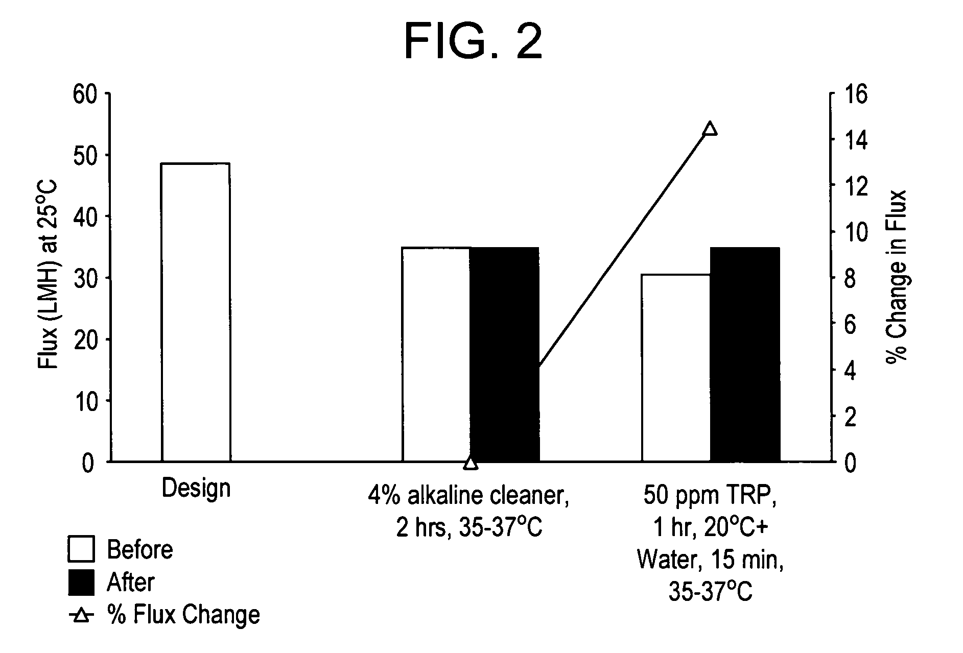
[0087]A spiral wound polyamide reverse osmosis membrane element that was mainly bio-fouled in a water treatment application, was cut open to obtain a test coupon (0.0138 m2 area). The cleaning performance was determined with the following test sequence. Test conditions for measurement of NaCl solution flux (permeate flow per unit time per unit membrane area) before and after cleaning were: 150 psi feed pressure, 1 Lit / min cross-flow rate, 2000 ppm NaCl in deionized water and 25° C. NaCl rejection was determined from feed and permeate conductivity measurements. TRP was poly(N-isopropyl acrylamide). Permeate flow was measured by a flow meter. A bucket and stopwatch could also be used.

Step1Baseline performance with 2000 ppm NaCl solution for 4 hrs to getflux and rejection value with fouled membrane before cleaning2Alternate circulation (10 min, 1 Lit / min cross-flow rate) andsoaking (10 min) of TRP solution in DI water for 1 hr at 20° C.and 25–35 psi feed pressure3Alternate circulation ...

example 2

[0091]The protocol for Example 2 is the same as that of Example 1, except in this example, 100 ppm TRP was used instead of 50 ppm and instead of water, 4% warm (above LCST) alkaline cleaner was used after TRP solution treatment. The results are shown in FIG. 4. In this example, higher TRP dosage and alkaline cleaner resulted in about 29% increase in flux compared to no change with alkaline cleaner alone. FIG. 5 shows that salt rejection increased to 97.2% with 100 ppm TRP followed by warm (above LCST) alkaline cleaner.


PUM

PropertyMeasurementUnit
molecular weightaaaaaaaaaa
temperatureaaaaaaaaaa

Abstract

A method of cleaning a fouled or a scaled RO or NF membrane surface with a solution containing one or more thermo-responsive polymers is disclosed. More specifically, the method comprises: treating the membrane surface in a membrane separation system with a solution containing one or more TRP, wherein said TRP is soluble in said solution and at least an effective amount of said TRP diffuses into a foulant layer on said membrane surface; making insoluble said TRP diffused into said foulant layer; optionally, rinsing the membrane.

Description

FIELD OF THE INVENTION[0001]This invention pertains to a method of cleaning fouled or scaled reverse osmosis (RO) and nanofiltration (NF) membranes using thermoresponsive polymers.BACKGROUND[0002]Membrane separation, which uses a selective membrane, is an increasingly common method of processing of liquid streams, such as in water purification. In membrane separation, constituents of the influent typically pass through the membrane as a result of a driving force(s) in one effluent stream called permeate thus leaving behind some portion of the original constituents in a second stream called concentrate or reject. Membrane separations commonly used for water purification or other liquid processing include the pressure driven processes of microfiltration (MF), ultrafiltration (UF), nanofiltration (NF), and reverse osmosis (RO). The performance of membrane separation, such as efficiency (e.g. flux, membrane permeability, permeate recovery, permeate quality, energy efficiency, time betwe...

Claims


Application Information

Patent Timeline
Patent Type & Authority Applications(United States)
IPC IPC(8): B08B9/00
CPCB01D65/02B01D2321/162B01D2321/164C02F2303/16B01D2321/168C02F1/441B01D2321/166
Inventor MUSALE, DEEPAK A.ZEIHER, E. H. KELLE
Owner DISCUS DENTAL LLC
Learn More