
Crucible having a doped upper wall portion and method for making the same

Active Publication Date: 2008-06-19
SHIN ETABU QUARTZ PRODS
View PDF18 Cites 21 Cited by
  • Summary
  • Abstract
  • Description
  • Claims
  • Application Information

AI Technical Summary

Benefits of technology

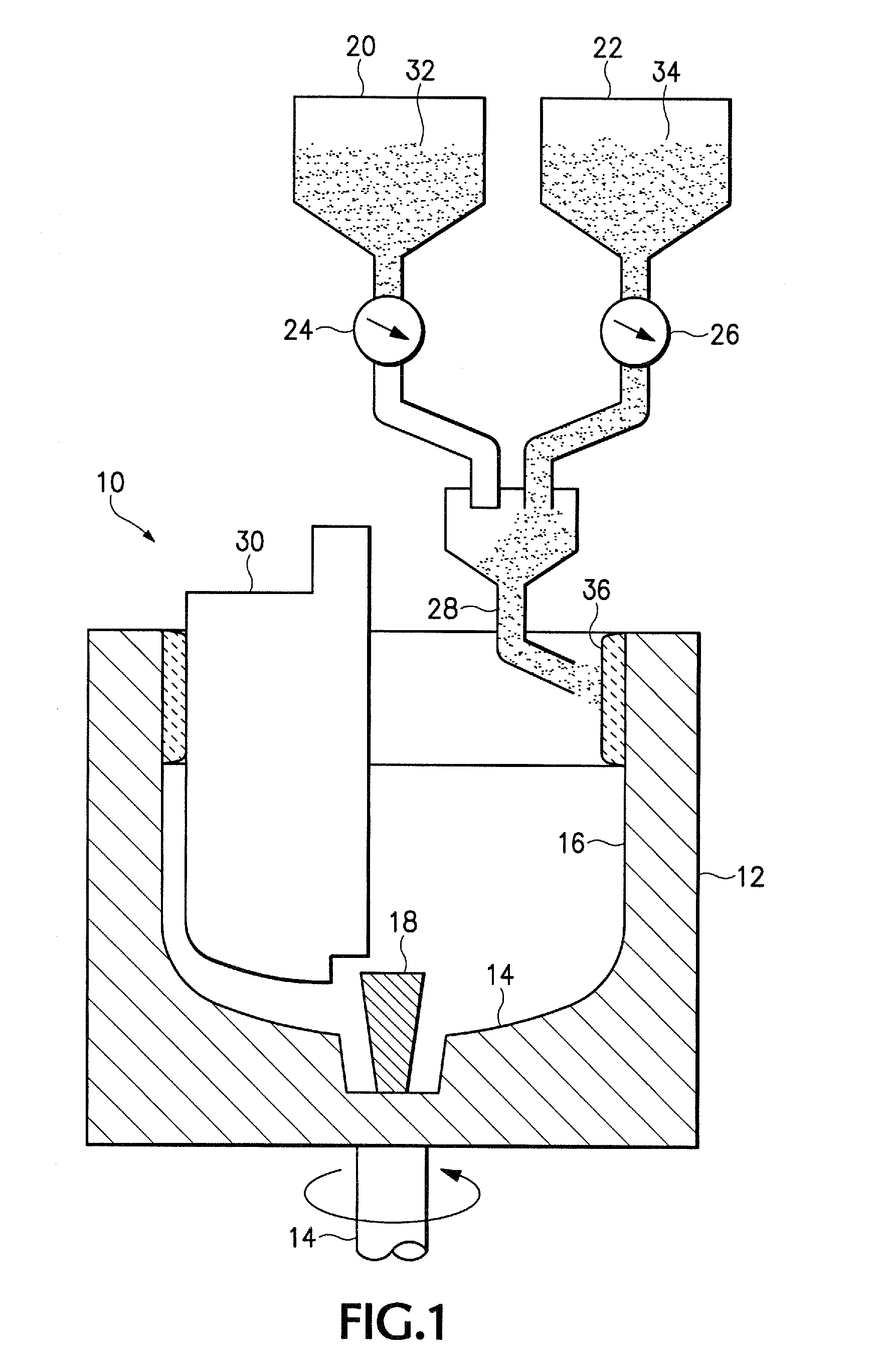
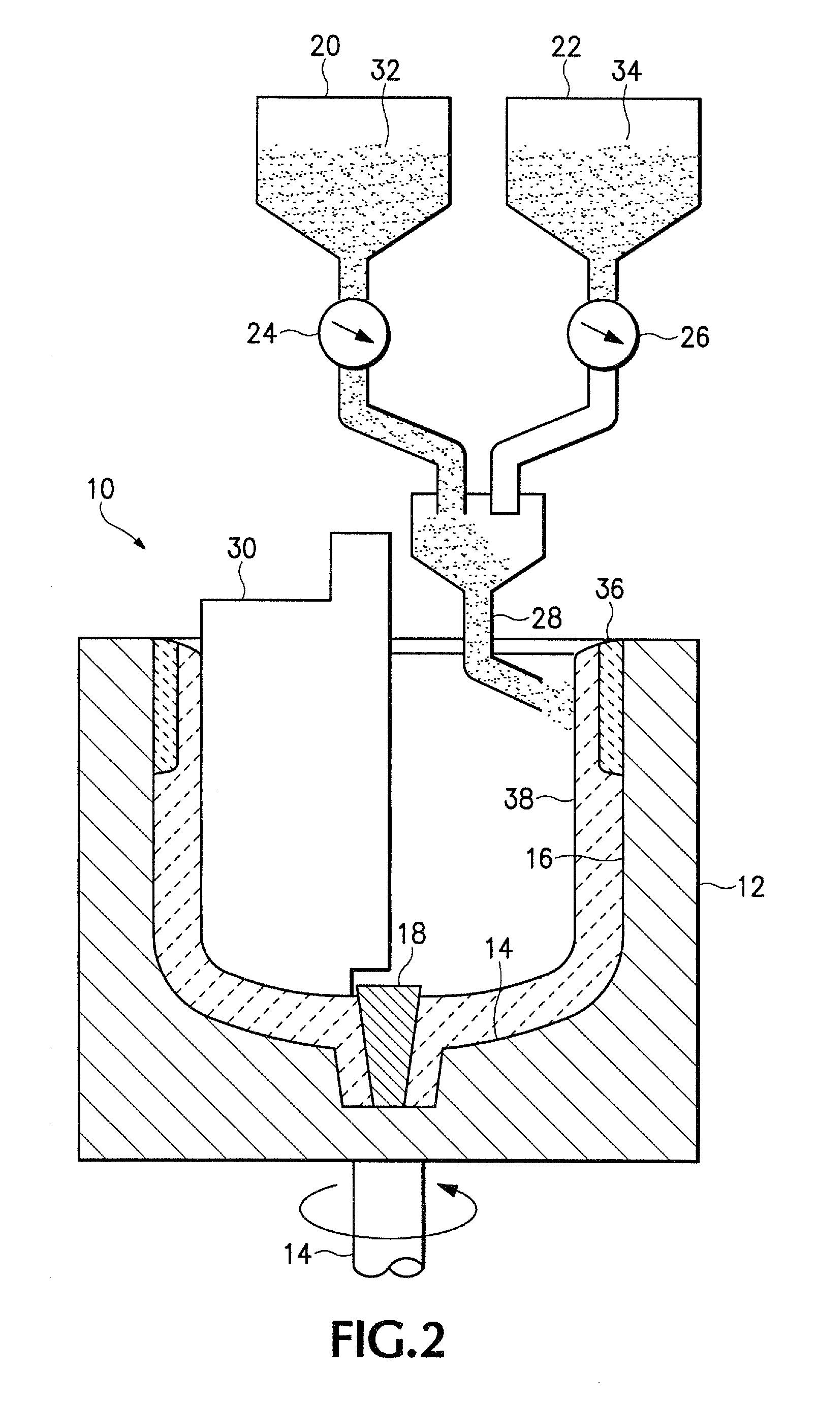
[0008]The melt line is the intersection of the surface of the molten silicon and the crucible wall. Because the wall above the melt line is not pressed into the susceptor by the weight of the melt, i.e., it is standing free, it may deform. It is difficult to control the heat to melt the silicon, and keep it molten, while preventing the wall above the melt line from sagging, buckling or otherwise deforming. Maintaining precise control over the heat slows down the CZ process and thus throughput of silicon ingots.

Problems solved by technology

It is difficult to control the heat to melt the silicon, and keep it molten, while preventing the wall above the melt line from sagging, buckling or otherwise deforming.
This prior art approach produces at least two kinds of problems, depending on the level of doping.
But when the doping level is high enough to support the upper wall, that portion of the wall beneath the melt line is subject to very high heat during the CZ process.
As a result of the prolonged heat and thick crystalline layer, the wall beneath the melt line may crack.

Method used


Image

  • Crucible having a doped upper wall portion and method for making the same
  • Crucible having a doped upper wall portion and method for making the same
  • Crucible having a doped upper wall portion and method for making the same

Examples


example a

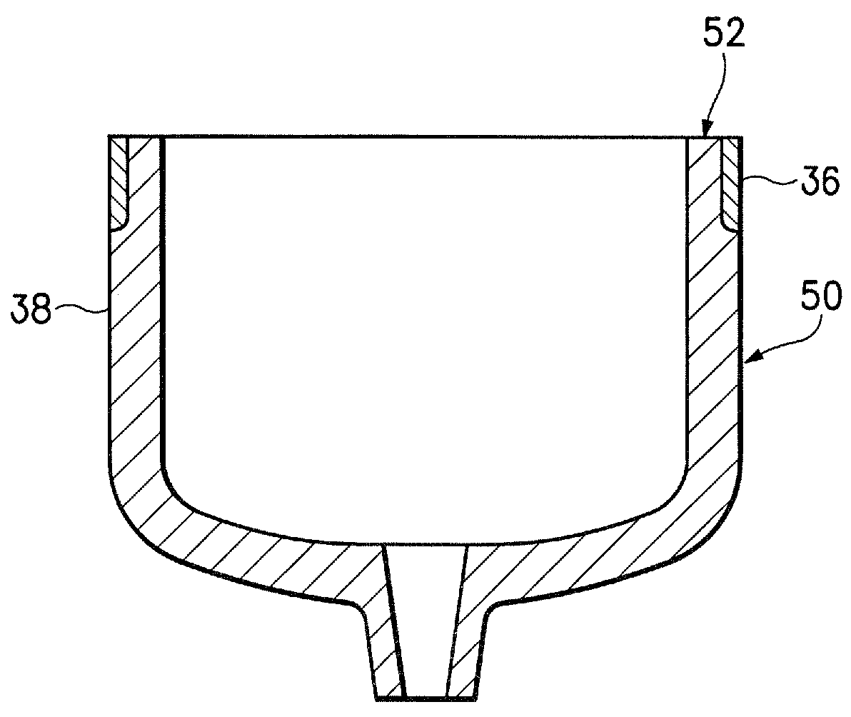
[0030]A crucible like crucible 50 was formed that has a height of 400 mm, 270 mm inner diameter, and 10 mm wall thickness. In this example the crucible was doped with 100 ppm aluminum to form a collar, like collar 36 that extends 150 mm down from rim 52. The collar is 1.4 mm thick and defines an outermost and uppermost surface of the crucible as shown in the drawing. A charge of 120 kg metallic silicon was charged and kept in the crucible for 120 hours without problems.

example b

[0031]A crucible like crucible 50 was formed that has a height of 400 mm, 270 mm inner diameter, and 10 mm wall thickness. In Example B the crucible was doped with 500 ppm aluminum to form a collar, like collar 36 that extends 50 mm down from rim 52. The collar is 1.6 mm thick and defines an outermost and uppermost surface of the crucible as shown in the drawing. A charge of 120 kg metallic silicon was charged and kept in the crucible for 120 hours without problems.

example c

[0032]A crucible like crucible 50 was formed that has a height of 400 mm, 270 mm inner diameter, and 10 mm wall thickness. In this example the crucible was doped with 100 ppm aluminum to form a collar, like collar 36 that extends 310 mm down from rim 52, which is substantially all of the generally upright outer wall of the crucible. The collar defines an outermost and uppermost surface of the crucible as shown in the drawing. A charge of 120 kg metallic silicon was charged and in the crucible. In this example, the melt overlaps substantially with the collar. Put differently, the melt line was substantially above the lower edge of the collar. After 50 hours of holding the melt, the crucible showed cracking between the substantially upright wall portion and the substantially horizontal bottom portion. This cracking results from the melt being in close proximity to the doped, and therefore crystallized, collar.

[0033]Although the examples each use aluminum as a dopant, it should be appr...


PUM

PropertyMeasurementUnit
Lengthaaaaaaaaaa
Fractionaaaaaaaaaa
Fractionaaaaaaaaaa

Abstract

A fused glass crucible includes a collar of doped aluminum silica that defines uppermost and outermost surfaces of the crucible. The melt line that defines the surface of molten silicon in the crucible may be substantially at the lower end of the collar or slightly above it. Crystallization of the collar makes it hard and therefore supports the remaining uncrystallized portion of the crucible above the melt line. The melt line may also be below the lower end of the collar, especially if the melt is drawn down or poured early in the process. Because there is little or no overlap or because the overlap does not last long, the doped aluminum collar is not damaged by the heat of from the melt.

Description

SUMMARY OF THE INVENTION[0001]1. Field of the Invention[0002]The present invention relates to the field of silica crucibles and more particularly to a silica crucible having a doped layer formed in the wall.[0003]2. Background of the Invention[0004]The Czochralski (CZ) process is well-known in the art for production of ingots of single crystalline silicon, from which silicon wafers are made for use in the semiconductor industry.[0005]In the CZ process, metallic silicon is charged in a silica glass crucible housed within a susceptor. The charge is then heated by a heater surrounding the susceptor to melt the charged silicon. A single silicon crystal is pulled from the silicon melt at or near the melting temperature of silicon.[0006]In addition to the CZ process, fused silica crucibles are used to melt metallic silicon, which is then poured—from a nozzle formed into the crucible—into a mold to create a polycrystalline silicon ingot, which is used to make solar cells. As with the CZ cr...

Claims


Application Information

Patent Timeline
IPC IPC(8): C30B15/10B22D7/06
CPCC03B19/095C03B2201/32C30B15/10Y10T117/1052Y10T117/1072Y10T117/1032Y10T117/10C30B29/06
Inventor KEMMOCHI, KATSUHIKOOHAMA, YASUO
Owner SHIN ETABU QUARTZ PRODS
Learn More