
Scanning thermal probe microscope

Inactive Publication Date: 2008-11-11
BRUKER NANO INC
View PDF14 Cites 44 Cited by
  • Summary
  • Abstract
  • Description
  • Claims
  • Application Information

AI Technical Summary

Benefits of technology

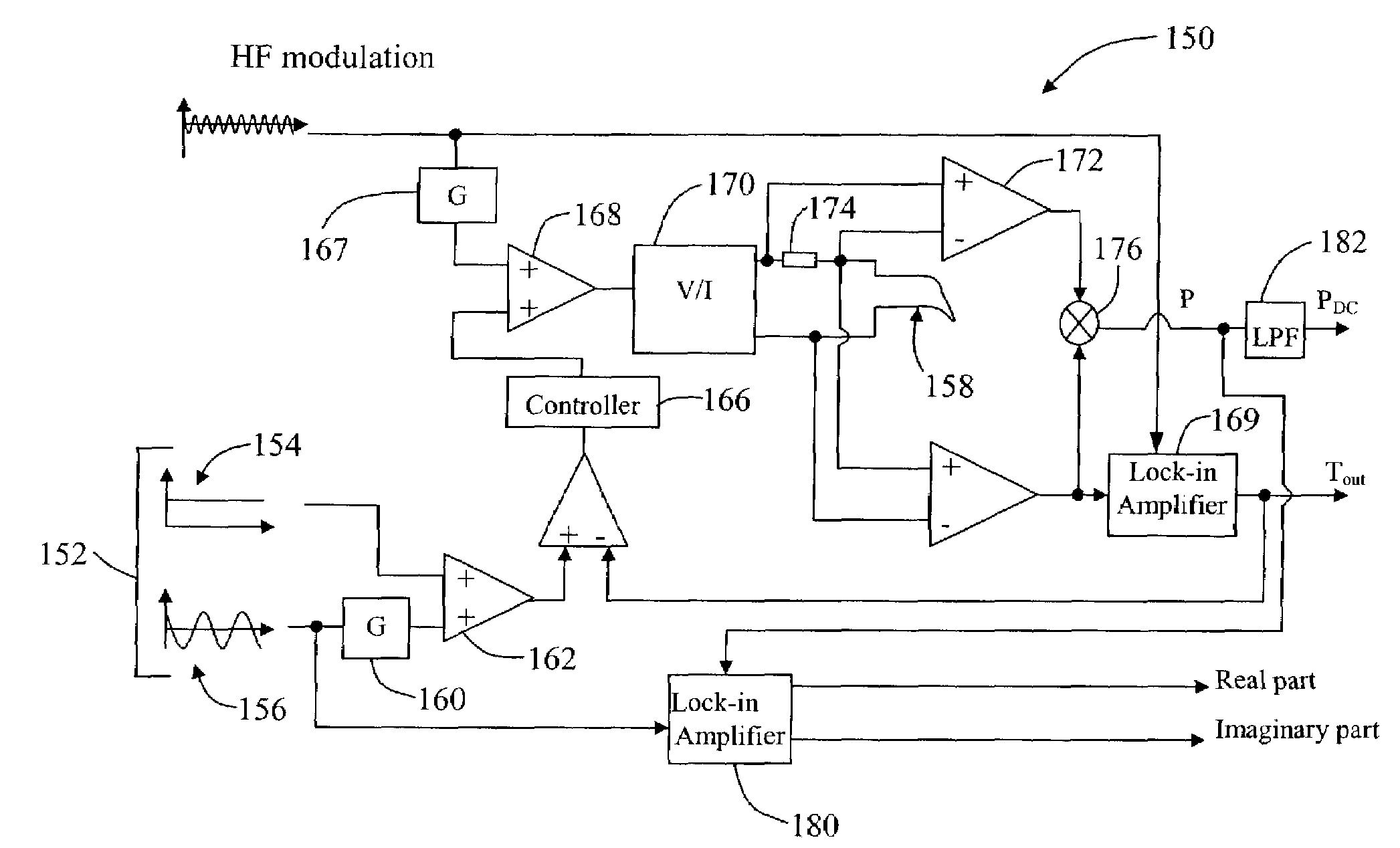
[0020]The preferred embodiment overcomes the above-noted drawbacks by providing a scanning thermal probe microscope that separates the sample signal from contamination introduced by the probe itself, thus providing improved range and sensitivity when making thermal measurements. Also, the preferred embodiment measures temperature directly and continuously. This is achieved by using an independent AC current to measure the temperature, a current the amplitude of which is kept constant. As a result, the preferred embodiment is able to operate in a temperature monitoring mode using a selected power input, rather than in a power monitoring mode for a given temperature which as known in the art is difficult to control. In one preferred embodiment, three components of current are provided to operate the thermal probe, a separate high frequency AC current to measure probe temperature, and a low frequency AC current and a DC current to provide a temperature command to heat / cool the sample.

Problems solved by technology

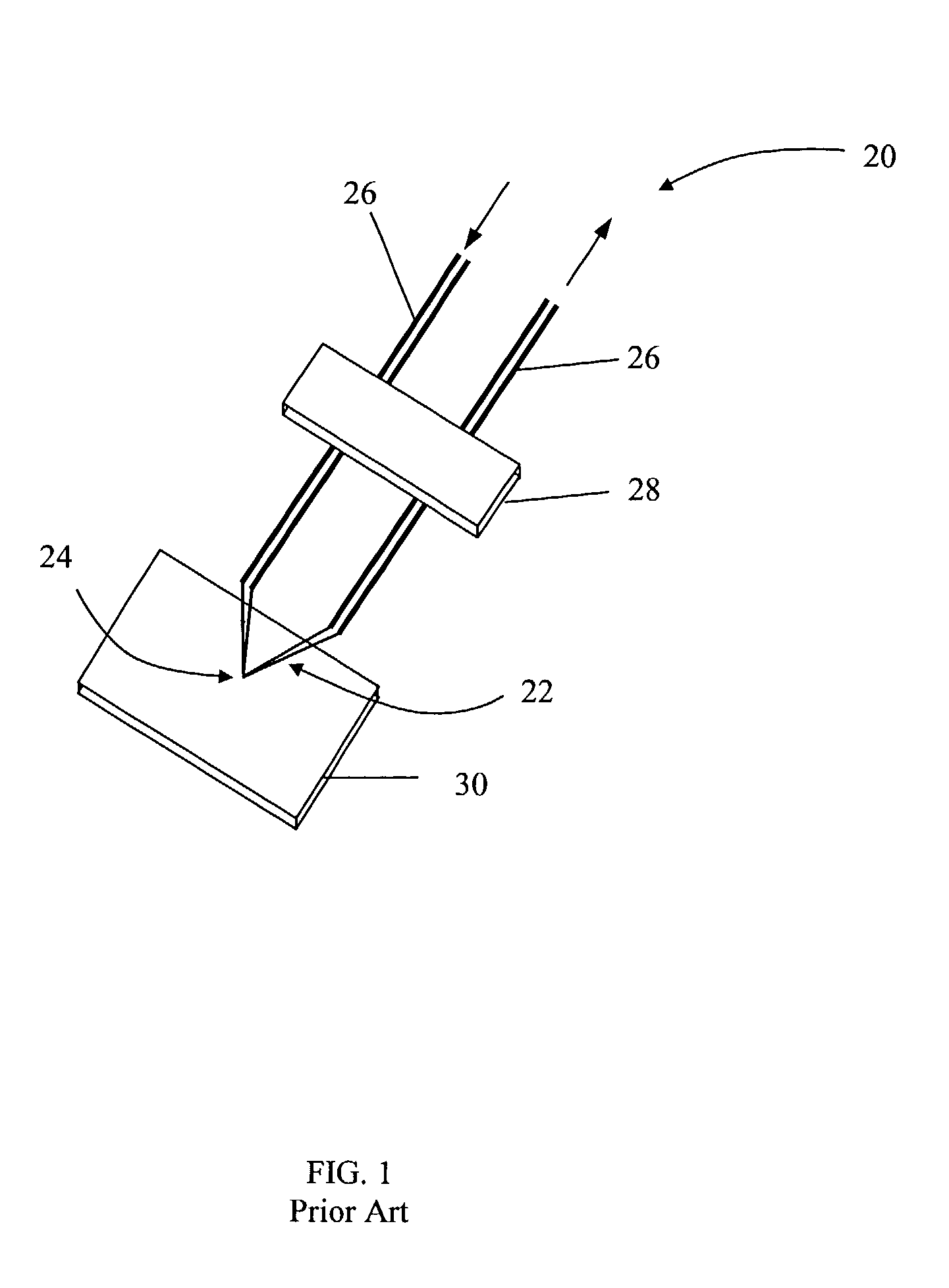
However, its functions are limited in that it cannot measure thermal properties such as conductivity and phase transitions because it only constitutes a temperature sensor, i.e., it cannot heat a sample.
In all of the above-described systems, notably, the system cannot measure thermal properties of a sample that change with temperature.
However, due to the difficulty to integrate a separate thermometer on a tiny tip, these alternatives are typically exclusively resistive probes, which serve as both a heater and a thermometer.
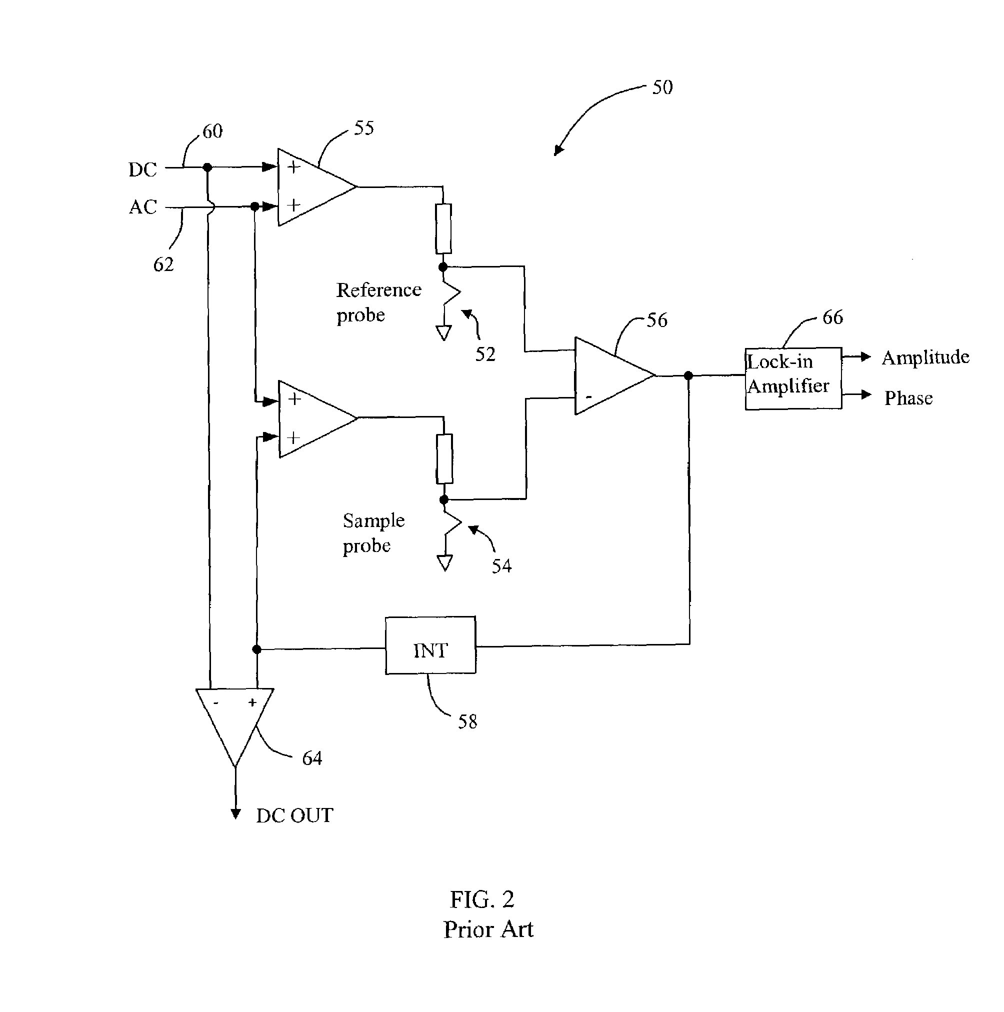
However, one problem with this technique is that it does not provide reliable data.
In particular, the system cannot separate the sample signal from contamination in the data caused by the probe itself.
As a result, the output is so heavily contaminated that its absolute value (i.e., using the reference probe) provides no useful information concerning the sample.
Another drawback of this latter system is that it does not employ a reliable scale of temperature, or provide any control thereof.
As the two probes are kept at the same voltage, the temperatures are necessarily different, thus injecting errors in the data.
And, because the signal used to measure the temperature is changing (i.e., the heating current is variable) a true measure of temperature cannot be obtained.
In addition, when a small AC current is used for heating, the effective noise associated with the temperature measurement is amplified, causing the data to be unreliable.

Method used


Image

  • Scanning thermal probe microscope
  • Scanning thermal probe microscope
  • Scanning thermal probe microscope

Examples


Embodiment Construction

[0056]The preferred embodiments are directed to a scanning thermal probe microscope for providing thermal analysis using an atomic force microscope. The scanning thermal microscope can image thermal properties of a region of a sample and perform localized thermal analysis at a point of interest. The microscope may combine the ability to obtain a typical AFM image (such as of surface topography) together with thermal images. In this regard, thermal images and typical AFM images may be obtained simultaneously. Depending on experiment criteria, the user typically will select a location of interest for performing local thermal analysis. Notably, with respect to appropriately positioning the probe for performing a localized thermal measurement, a positioning system is required. One such apparatus is shown and described in U.S. Pat. No. 6,530,268, and U.S. Ser. No. 09 / 803,268, both assigned to the present assignee, the contents of which are hereby expressly incorporated by reference.

[0057...


PUM


Abstract

An apparatus and method of measuring a parameter associated with a sample is provided. The method includes providing a probe adapted to heat the sample and applying a measuring current having a frequency ω1 to the probe. In operation, the method measures the amplitude of the voltage across the probe at a frequency ω1. This amplitude is indicative of a temperature of the probe. The preferred embodiment also provides a method of separating contamination of the thermal data caused by the probe from thermal data associated with the sample under test.

Description

BACKGROUND OF THE INVENTION[0001]1. Field of the Invention[0002]The present invention is directed to scanning probe microscopes, and more particularly, a scanning thermal probe microscope employing a thermal probe as both a heat source and a temperature sensor for imaging and sensing thermal properties of a sample.[0003]2. Description of Related Art[0004]Modern materials science is increasingly concerned with the analysis and control of materials at a very small scale. Micro thermal analysis is directed to thermal analysis in conjunction with microscopy techniques using a thermal probe capable of providing thermal excitation. The use of microscopy allows small-scale regions of a sample to be selected for such imaging, for example. Micro thermal analysis is currently being used commercially to characterize various samples such as polymers, biological materials and electronic materials, among other types of samples. Notably, any local disturbance of the structure that results in a cha...

Claims


Application Information

Patent Timeline
IPC IPC(8): G01K7/16G01K13/00G01K3/00G01N25/20
CPCB82Y35/00G01Q60/58G01N25/4833
Inventor WANG, CHUNHAI
Owner BRUKER NANO INC
Learn More