X-ray radiator with a thermionic photocathode

a thermionic photocathode and x-ray radiator technology, which is applied in the direction of x-ray tube cathode assembly x-ray tube cooling, etc., can solve the problems of focusing electron beams, generating soft x-ray radiation, and the use of such an x-ray tube is only in a limited manner, so as to achieve good vacuum stability and low laser power , the effect of easy mechanical handling

Inactive Publication Date: 2007-11-29
SIEMENS AG
View PDF4 Cites 6 Cited by
  • Summary
  • Abstract
  • Description
  • Claims
  • Application Information

AI Technical Summary

Benefits of technology

[0013] An object of the present invention is to provide an x-ray radiator suitable for use in medical radiology, with a laser-activated cathode with which a sufficient x-ray power can be generated with relatively low laser power and with which a simple and efficient cooling of the system enables a rapid reuse capability.
[0019] The use of a surface-roughened cathode surface causes incident laser light to be repeatedly scattered on the surface so as to be more strongly absorbed. The reflectivity is thereby reduced and the injection efficiency of the employed laser power is increased. The cathode surface is advantageously roughened by a sintering process. Given use of a likewise sintered cathode support (substrate), advantageously as a common, one-piece component, the further advantage is achieved that depending on porosity, the specific heat capacity and the density can be reduced (by the sintering structure) to between, for example, 40% and 80% of that of pure material; even less laser power is required in order to achieve the necessary emission laser temperature at the laser focus, but the heat conductivity is still sufficient to suitably cool the cathode. Porosity, for example for sintered tungsten, advantageously lie between 20% and 60%, preferably between 35% and 45%, in particular at approximately or exactly 40%. A porosity range can be set somewhat specifically in sintering, for example by the sinter duration, the sinter pressure, the density of the base body and so forth. Those skilled in the art can achieve a compromise between reduced heat conductivity and decreasing durability of the work piece. The object is also achieved by the specified materials, which exhibit a suitably porosity without exhibiting a significant roughness (or vice versa). From the viewpoint of a high effectiveness a combination of both properties is particularly advantageous. The use of tungsten-rhenium as a cathode material is also advantageous, possibly with admixtures of thorium.
[0020] The use of a doped material in the cathode surface achieves a decrease in the electron work function. The operating temperature of the electron emitter thus can be distinctly lowered, whereby (i) less laser power is required and (ii) the vapor pressure of the cathode is even lower, such that high voltage field gradients can be applied. The doped cathode base material preferably has at least one material from the group comprising of tungsten, molybdenum and tantalum; thus, for example, essentially pure W, Mo and Ta or a mixture thereof. In particular, use of tungsten as a base material (matrix material) with La2O3 and / or CeO as doping agents is advantageous. The doping degree advantageously lies between 0.5% and 20%. For example, for pure thorium as a doping agent a material proportion around 1% is advantageous. The doping, possibly together with a surface roughening, preferably lowers the electron work function to below 3.5 eV, especially to 1.5 eV to 3.5 eV.
[0034] All inventive materials listed above achieve the object and have the effect that a lower laser power is required for a temperature increase, a good vacuum stability of an x-ray radiator can be achieved and the cathode remains easy to handle mechanically.

Problems solved by technology

This creates problems in the focusing of the electron beam.
Among other things, a problem occurs in the generation of soft x-ray radiation given which a comparably low voltage is applied between cathode and anode.
The use of such an x-ray tube is possible only in a limited manner for specific applications (such as, for example, mammography).
The practical feasibility of this concept, however, appears to be questionable due to the quantum efficiency of available photo-cathodes and the light power that is required.
Given use of high light power, the cooling of the photo-cathode requires a considerable expenditure due to its rather low heat resistance.
In view of the vacuum conditions that exist in x-ray tubes, the surface of the photo-cathode is additionally subjected to oxidation processes, which limits the durability of such an x-ray tube.
The longer electron flight path with repeated deflection of the electron beam between the dynodes, however, requires a high expenditure for focusing the beam.
The surface of the cathode should be capable of being heated and cooled quickly in the disclosed embodiment of the cathode with a substrate layer made of a material with high heat conductivity, but this appears to be problematic with regard to the light power that is required.

Method used


Image

  • X-ray radiator with a thermionic photocathode
  • X-ray radiator with a thermionic photocathode

Examples


Embodiment Construction

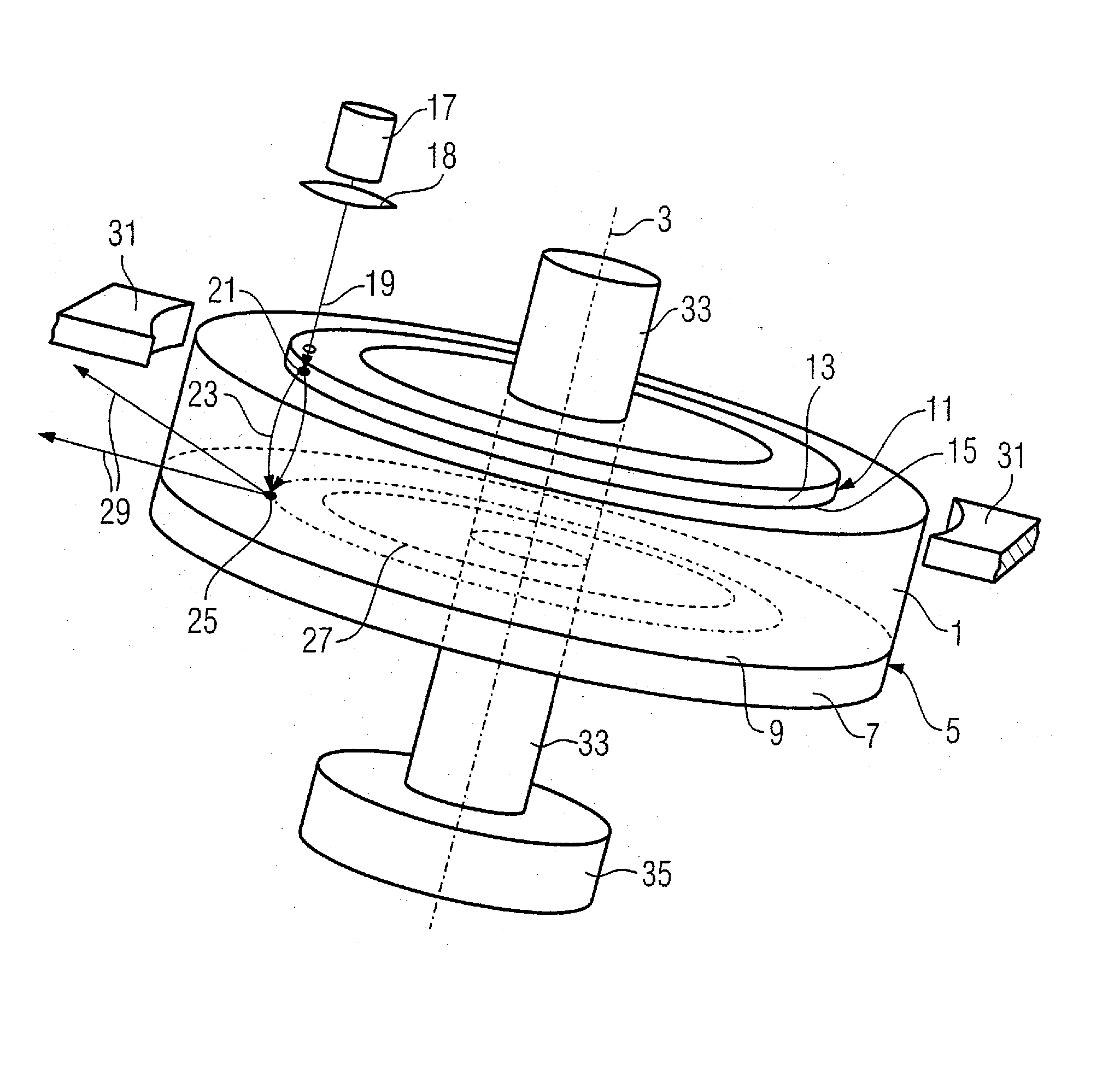
[0039] A three-dimensional representation of a vacuum housing 1 is shown in FIG. 1. The vacuum housing 1 is fashioned as a cylinder (having a cylinder jacket formed of an insulating material) and the cylinder is mounted in a rotationally symmetrical manner on an axis 3. An anode 5 forms a base of the cylinder. The anode 5 has a support layer 7 and an annularly-fashioned surface 9 from which x-rays 29 are emitted. An annularly-fashioned cathode 11 is located in the opposite base of the vacuum housing 1 (cylinder). The cathode 11 has a support layer 13 that is part of the exterior of the vacuum housing 1 and a surface 15 that facing the interior of the vacuum housing 1.

[0040] The anode 5 and cathode 11 shown in FIG. 1 are fashioned axially symmetrically, such that the electron beam or the laser beam always strikes the surface of the anode 5, or the cathode 11 during the rotation. However, it can also be advantageous to fashion the anode 5 and the cathode 11 (in particular their suppo...


PUM


Abstract

An x-ray radiator has an anode that emits x-rays when struck by electrons, a cathode that thermionically emits electrons upon irradiation thereof by a laser beam, a voltage source for application of a high voltage between the anode and the cathode for acceleration of the emitted electrons towards the anode to form an electron beam. A surface of the cathode that can be irradiated by the laser beam is at least partially roughened and / or doped and / or is formed of an intermetallic compound or vitreous carbon.

Description

BACKGROUND OF THE INVENTION [0001] 1. Field of the Invention [0002] The present invention concerns an x-ray radiator with a cathode and an anode, of the type wherein the cathode has a surface that emits electrons upon laser irradiation of the surface. [0003] 2. Description of the Prior Art [0004] High-capacity x-ray radiators typically have an anode that is mounted to rotate in order to ensure a high thermal loading capability of the anode during generation of x-rays with high radiation power. [0005] DE 87 13 042 U1 describes an x-ray tube with an evacuated housing (the housing is evacuated in order to be mounted such that it can be rotated around a rotation axis) in which a cathode and an anode are arranged. The cathode and the anode are connected in a fixed manner with the housing. The x-ray tube has drive means for rotation of the housing around the rotation axis. A deflection system that is stationary relative to the housing deflects an electron beam proceeding from the cathode ...

Claims


Application Information

Patent Timeline
Patent Type & Authority Applications(United States)
IPC IPC(8): H01J35/06
CPCH01J35/065H01J35/16H01J2235/162H01J2235/066H01J2235/1216H01J2235/062
Inventor FREUDENBERGER, JOERGFRITZLER, SVENFUCHS, MANFREDMATTERN, DETLEFROEHRER, PETERSCHARDT, PETER
Owner SIEMENS AG
Why Eureka
Try Eureka