
Catalyst

Inactive Publication Date: 2007-07-12
TANAKA PRECIOUS METAL IND
View PDF9 Cites 46 Cited by
  • Summary
  • Abstract
  • Description
  • Claims
  • Application Information

AI Technical Summary

Benefits of technology

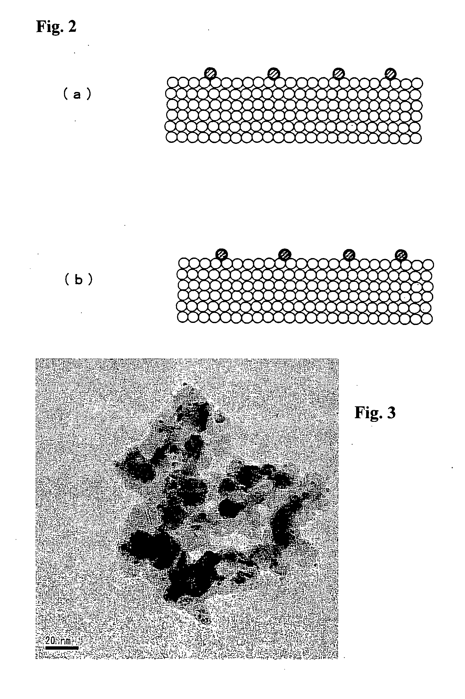
[0012] The second means is the selection of a desirable carrier. Oxides such as alumina which are generally used in conventional catalysts have a weak interaction with transition metals which are used as catalytic metals, and tend to cause catalytic metals to migrate relatively easily also after they support the catalytic metals. Therefore, the present inventors have thought that by using a porous oxide which has a large constraining force working on transition metals, it is possible to suppress the migration of catalytic metals even at high temperatures and hence it is possible to suppress the coarsening of catalyst particles and the deactivation of catalysts.
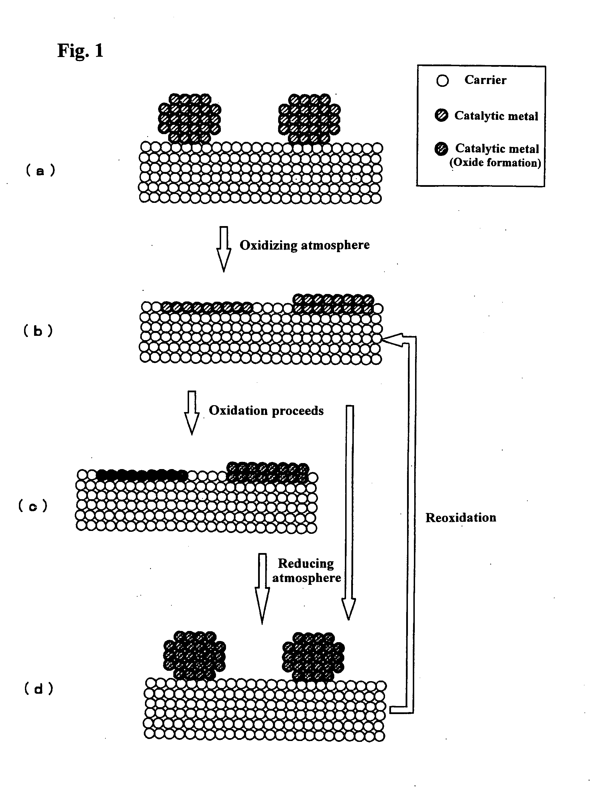
[0017] When this catalyst is in an oxidizing atmosphere, it comes to a state as shown in FIG. 1(b). Examples of an environment in which the catalyst takes this morphology include a case where after catalyst particles are supported by a carrier, the catalyst is subjected to calcining treatment in the air at temperatures of 400 to 500° C. or so, a case where the catalyst is used at these temperatures, and a case where the catalyst is heated in a high-temperature environment at not lower than 800° C. for a short time. When the catalyst is in this state, the catalyst particles develop into planar aggregates. Although the catalyst particles form a single layer of multiple layers having 1 to 5 atoms or so, the catalyst has high catalytic activity because the catalyst particles are still in cluster shape. In a catalyst in which catalyst particles in this state are supported on a carrier, the catalyst particles are fixed by a strong interaction with the carrier. Therefore, the catalyst particles do not easily migrate and the catalyst has the best durability and can maintain its high activity. Furthermore, because the catalyst particles in this state are formed in an oxidizing atmosphere, a complex oxide of a rare earth element and a transition metal element may sometimes be formed.
[0022] Although a carrier used in the present invention is made of a porous metal oxide containing ceria and may be formed only from ceria alone, it may be in a condition mixed with other metal oxides such as alumina and silica. Particularly, mixtures of rare earth metal oxides, such as a ceria-zirconia mixture oxide, in which zirconia is mixed with ceria, and a ceria-zirconia-yttria mixture oxide, in which zirconia and yttria are mixed with ceria, are desirable carriers from the standpoint of an improvement of the heat resistance of the carrier. It is desirable that the rare earth oxide content of this porous carrier be 15 to 100 wt %.
[0028] As described above, the catalyst of the present invention is a catalyst in which a porous carrier made of a ceria-containing organic oxide is used and the particle size (number of atoms) of catalyst particles is adjusted during the formation of the porous carrier. The catalyst of the present invention exhibits high reaction activity and has high durability because the coarsening of catalyst particles caused by use for a long time is suppressed.
[0029] The catalyst of the present invention changes its morphology by being subjected to a reducing atmosphere after its use (in an oxidizing atmosphere) and at the same time, the catalytic function is reproduced. Therefore, as a method of using the catalyst of the present invention, it is possible to reproduce the catalytic function by performing reducing treatment, which involves heat treating a catalyst after use in a reducing atmosphere, and to reuse the catalyst.
[0030] The catalyst of the present invention is useful as a catalyst for general gasoline engine and besides as a catalyst for diesel engine and a catalyst for lean burn engine. Particularly in the case of a gasoline engine, because a rich atmosphere and a lean atmosphere repeat periodically in a very short time, the catalyst can exhibit catalytic activity which is almost the same as immediately after its manufacture for a long time while repeating consumption and regeneration. Also in the case of a lean burn engine, because rich gas is periodically fed as a spike to the catalyst, the regeneration effect by reduction is expected during the operation of the engine and the catalyst can be used for a long period while repeating consumption and regeneration.

Problems solved by technology

This is because in conventional catalysts, even when catalyst particles are caused to aggregate by the heating after being supported, it is difficult to cause the catalyst particles to aggregate to a desirable number of atoms, and there is a limit to an improvement of activity.

Method used


Image

  • Catalyst
  • Catalyst
  • Catalyst

Examples


example 1 (

Pt / CZO Catalyst)

[0038] A metal salt solution was prepared by diluting 22.01 g of a nitric acid solution of dinitrodiamine platinum (Pt concentration: 4.54 wt %) with distilled water to 100 mL in a measuring flask. On the other hand, 2.21 g of polyethylene imine (PEI) having an average molecular weight of 50000 were diluted with distilled water to 100 mL in a measuring flask. And 10 mL of the metal salt solution and 4 mL of the PEI solution were mixed and stirred, the mixed solution was then added dropwise to a solution in which 10 g of CZO were dispersed, ammonia was added dropwise until pH 10 was obtained, and a hybrid complex was caused to be adsorbed on a CZO carrier. The surface area of this CZO catalyst is 67 m2 / g and the cerium concentration is 40 mol %.

[0039] Next, a dispersion liquid in which this carrier is dispersed was heated to 70° C., 30 mL of an aqueous solution of 2.5 wt % hydrazine were added dropwise for a duration of one hour, and the dispersion liquid was held at...

example 2 (

Pt / Pd / CZO Catalyst)

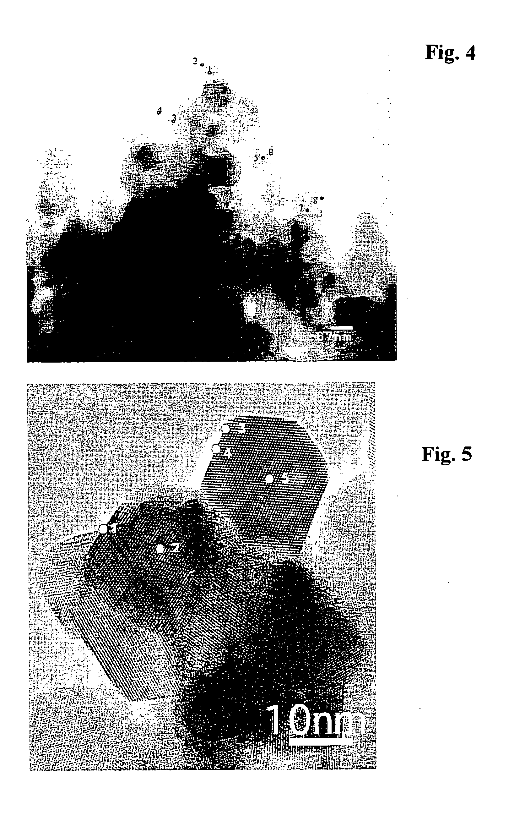
[0040] A mixture of 17.84 g of a nitric acid solution of dinitrodiamine platinum (Pt concentration: 4.54 wt %) and 4.32 g of a nitric acid solution of palladium dinitrate (Pd concentration: 4.40 wt %) was prepared, and this mixture was diluted with distilled water to 100 mL in a measuring flask, whereby a metal salt solution was obtained. And the same PEI solution as in Example 1 was added to 10 mL of this precious metal salt solution and other operations were performed by the same process as in Example 1, whereby a Pt / Pd / CZO catalyst was obtained. When the catalyst after drying was also observed under a TEM, the presence of particles of about 3 nm was verified. When an analysis by EDX was performed, the presence of Pt and Pd was verified within single particles.

example 3 (

Pt / Rh / CZO Catalyst)

[0041] A mixture of 18.06 g of a nitric acid solution of dinitrodiamine platinum (Pt concentration: 4.54 wt %) and 1.81 g of a solution of rhodium nitrate (Rh concentration: 10.0 wt %) was prepared, and this mixture was diluted with distilled water to 100 mL in a measuring flask, whereby a metal salt solution was obtained. And the same PEI solution as in Example 1 was added to 10 mL of this precious metal salt solution and other operations were performed by the same process as in Example 1, whereby a Pt / Rh / CZO catalyst was obtained. When the catalyst after drying was also observed under a TEM, the presence of particles of about 3 nm was verified. When an analysis by EDX was performed, the presence of Pt and Rh was verified within single particles.


PUM

PropertyMeasurementUnit
Particle sizeaaaaaaaaaa
Specific surface areaaaaaaaaaaa
Temperatureaaaaaaaaaa

Abstract

The present invention provides a catalyst comprising particles of one or more catalytic metals supported on a porous carrier made of one or more metal oxides, wherein the porous carrier is made of an oxide containing a rare earth oxide, and that the catalytic metal particles are made of one or more transition metals or transition metal oxides having 10 to 50000 atoms. In the present invention, cluster-like catalyst particles are supported on a specific carrier. The catalyst of the present invention maintains desirable activity while changing the morphology of catalyst particles by the atmosphere of the catalyst.

Description

TECHNICAL FIELD [0001] The present invention relates to a catalyst. More particularly, the present invention relates to a catalyst comprising a transition metal carried as catalyst particles. BACKGROUND ART [0002] Catalysts are used in various fields, in promoting reactions, such as reactions for the synthesis of compounds and reactions of fuel cells, and also in cleaning automobile emissions. In many catalysts which have hitherto been used, porous materials, such as oxides of alumina, silica and the like and carbon, are used as a carrier, and precious metals, such as platinum, palladium and rhodium, are supported by the carrier. In recent years, multicomponent catalysts in which multiple precious metals are supported to improve activity have been growing popular. Also with respect to carriers, in catalysts for treating automobile emissions, recent years have seen the use of carriers to which there are added ceria having oxygen adsorbing and releasing abilities and a ceria-zirconia ...

Claims


Application Information

Patent Timeline
IPC IPC(8): B01J23/10B01D53/94F01N3/10B01J21/06B01J23/00B01J23/63B01J35/00B01J35/10B01J37/02B01J37/14B01J37/16F01N3/28H01M4/90H01M4/92
CPCB01D53/945Y02T10/22B01D2255/206B01D2255/407B01D2258/012B01J21/066B01J23/002B01J23/63B01J35/0013B01J37/0203B01J37/14B01J37/16B01J2523/00H01M4/90H01M4/9075H01M4/92H01M4/925Y02E60/50B01D2255/10B01J2523/3712B01J2523/48B01J2523/822B01J2523/828B01J2523/824Y02A50/20Y02T10/12B01J35/23
Inventor SAITO, MASAYUKISAGAE, TAKEYUKI
Owner TANAKA PRECIOUS METAL IND
Learn More