
System and method for increasing accuracy of transmitter power detection over a larger range of output power levels

a transmitter power detection and output power technology, applied in the direction of automatic tone/bandwidth control, amplifier combination, gain control, etc., can solve the problems of reducing the accuracy of transmitting power at low output power levels, increasing cost, and a lot of extra circuitry, so as to improve temperature performance, high gain or low gain

Active Publication Date: 2007-04-12
CISCO TECH INC
View PDF6 Cites 8 Cited by
  • Summary
  • Abstract
  • Description
  • Claims
  • Application Information

AI Technical Summary

Benefits of technology

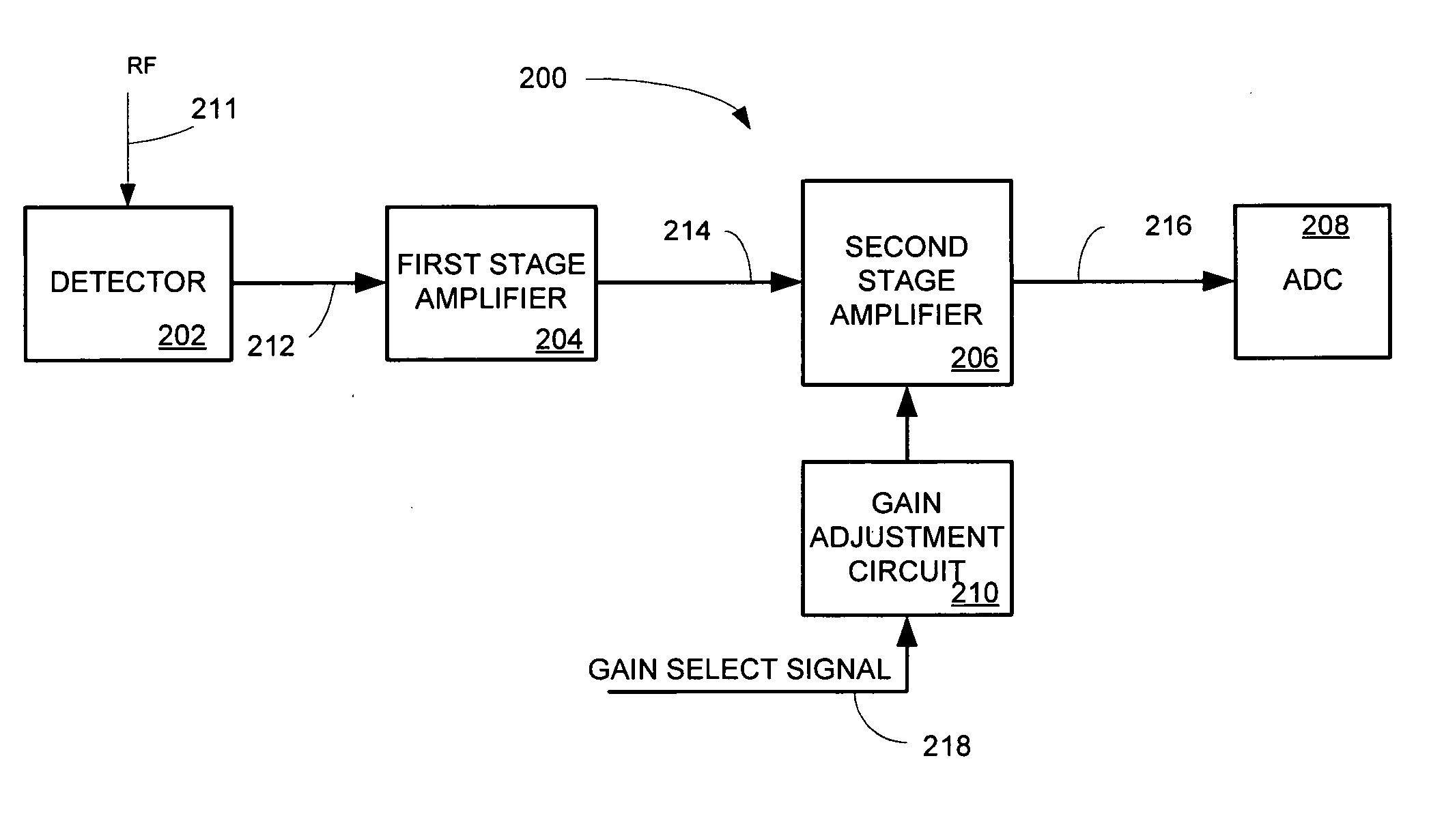
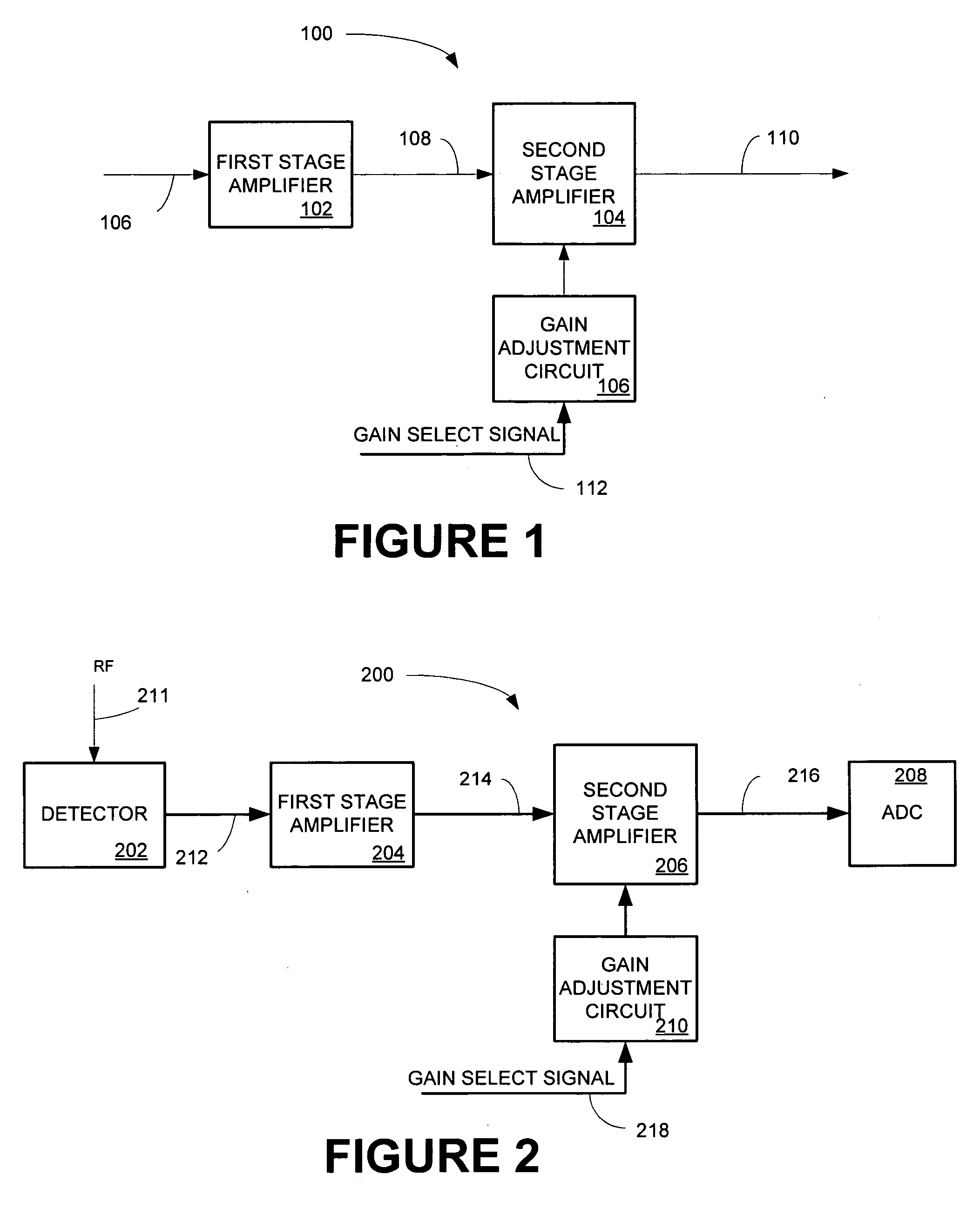
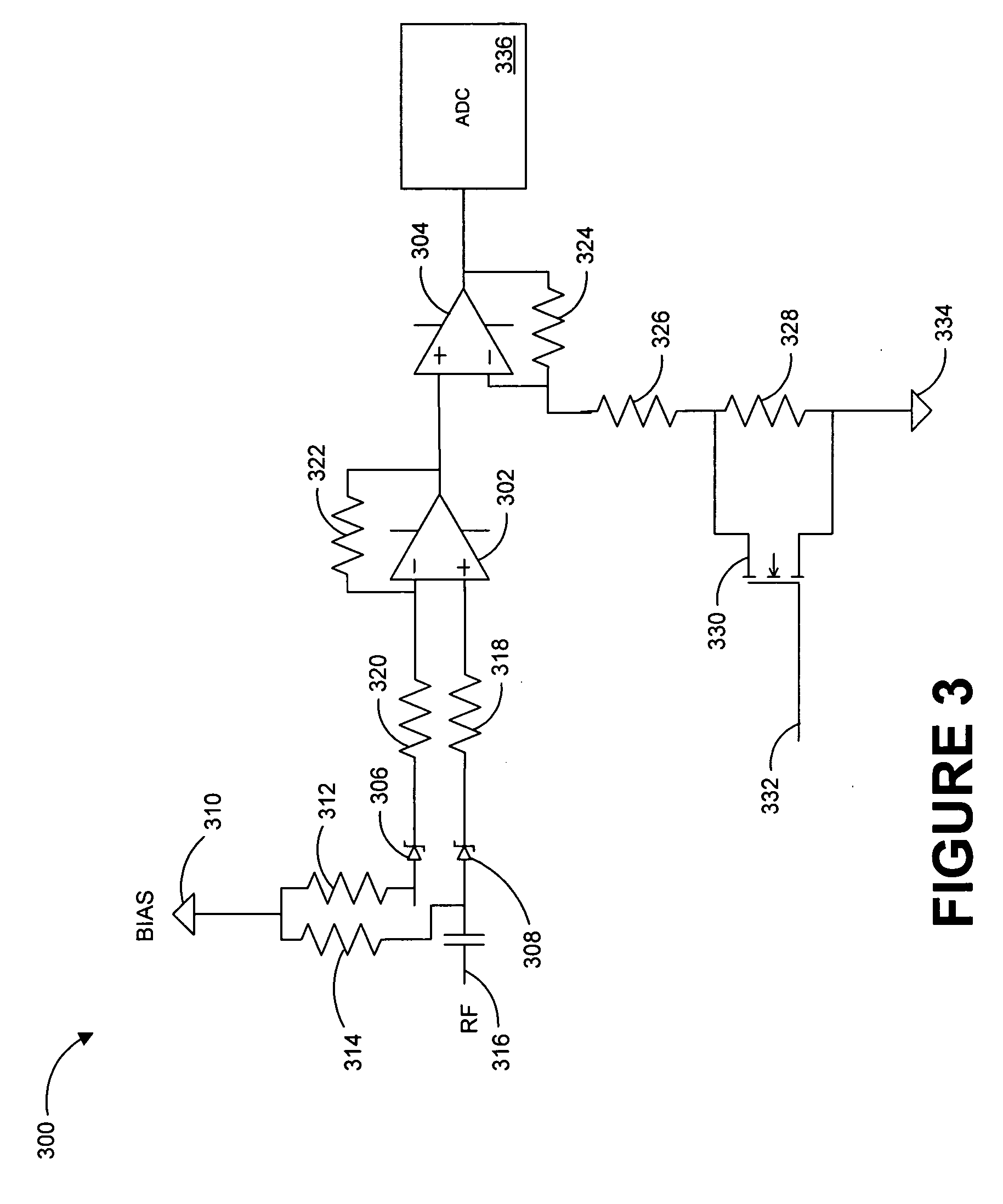
[0007] In accordance with an aspect of the present invention, there is described herein a system wherein a diode detector is followed by a series cascade of 2 op amps. The first op amp functions as a differential / buffer amplifier, which improves temperature performance. The second op amp has two selectable gain factors. The output of the second op amp is routed to the ADC. A single control can is connected to a controllable switching device that configures the second op amp for high gain or low gain.
[0011] In accordance with an aspect of the present invention, there is disclosed herein a method for increasing the accuracy of power detection. A signal having a signal strength is received. The received signal is amplified by a first amplifier. The gain of a second amplifier is adjusted based on the signal strength of the received signal. The amplified signal is amplified a second time by a second amplifier.
[0012] An aspect of the present invention is that it solves the problem inaccurate control of low target transmit output powers while still maintaining accuracy at higher power levels. The present invention has a minimal impact to cost, circuit complexity, and required PCB real estate when compared to prior art techniques.

Problems solved by technology

However, a problem arises because the detector diode response (output voltage vs. input power) is more sensitive (i.e. has a steeper sloop) for high transmit output power compared to low transmit output power levels.
Therefore, the nonlinear response of the diode sensor in the digital control loop reduces transmit power precision at low output power levels.
However, this approach required a lot of extra circuitry, which increased cost.
Furthermore, substantial printed circuit board (PCB) real estate was required to implement this solution as well as multiple control line routing.

Method used


Image

  • System and method for increasing accuracy of transmitter power detection over a larger range of output power levels
  • System and method for increasing accuracy of transmitter power detection over a larger range of output power levels
  • System and method for increasing accuracy of transmitter power detection over a larger range of output power levels

Examples


Embodiment Construction

[0020] Throughout this description, the preferred embodiment and examples shown should be considered as exemplars, rather than limitations, of the present invention. An aspect of the present contemplates a system for increasing the accuracy of power detection over a larger range of output power levels wherein a diode detector is followed by a series cascade of 2 op amps. The first op amp functions as a differential / buffer amplifier, which improves temperature performance. The second op amp has two selectable gain factors. The output of the second op amp is routed to the ADC. A single control can is connected to a controllable switching device that configures the second op amp for high gain or low gain.

[0021] For high target output power levels, the second op amp is configured for low gain. For low target output power levels, the second op amp is configured for high gain. High gain increases the sensitivity of the diode detector circuit response, which improves the accuracy of the t...


PUM


Abstract

A system and method for increasing accuracy of transmitter power detection over a larger range of output power levels wherein a diode detector is followed by a series cascade of 2 op amps. The first op amp functions as a differential / buffer amplifier, which improves temperature performance. The second op amp has two selectable gain factors. The output of the second op amp is routed to the ADC. A single control can is connected to a controllable switching device that configures the second op amp for high gain or low gain.

Description

BACKGROUND OF THE INVENTION [0001] An Access Point (AP) can have two transceivers for wireless local area network (WLAN or wireless LAN) applications, such as in the 2.4 GHz and 5 Ghz frequency bands. Both transmitters use a microwave detector diode to sense radio output power. The diode's output voltage is amplified and applied to an analog to digital converter (ADC). [0002] The ADC is part of the digital feedback control loop that is used for transmit automatic level control (ALC). The ALC adjusts the radio power to maintain a target output power at the transmit antenna port. For example, an AP target output power can range from 1 dBm to 20 dBm. [0003] The detector diode circuit response is centered to fit the range of the output voltages inside the ADC window (0 V to 2 V). With 8 bits of ADC resolution, an 8 mV change is required to change the ADC by one digital value. When the ADC value changes, the digital feedback loop makes the appropriate correction to maintain the target ou...

Claims


Application Information

Patent Timeline
IPC IPC(8): H03G3/20
CPCH03F1/34H03F3/211H03F3/24H03F3/45475H03F2200/105H03F2200/99H03G1/0088
Inventor GIATIS, PETROSJOHNSON, GERALD B.SIMON, FRANKLIN D. JR.METSKER, COREY
Owner CISCO TECH INC
Learn More