
Method and apparatus for forming melt spun nonwoven webs

a thermoplastic polymer and non-woven technology, applied in the direction of chemistry apparatus and processes, manufacturing tools, other domestic objects, etc., can solve the problems of filament breakage, high air and fiber velocities so as to achieve uniform cross-machine uniformity control, constant filament distribution, and limited machine width

Active Publication Date: 2007-03-15
HARTGE HILLS DEV
View PDF10 Cites 104 Cited by
  • Summary
  • Abstract
  • Description
  • Claims
  • Application Information

AI Technical Summary

Benefits of technology

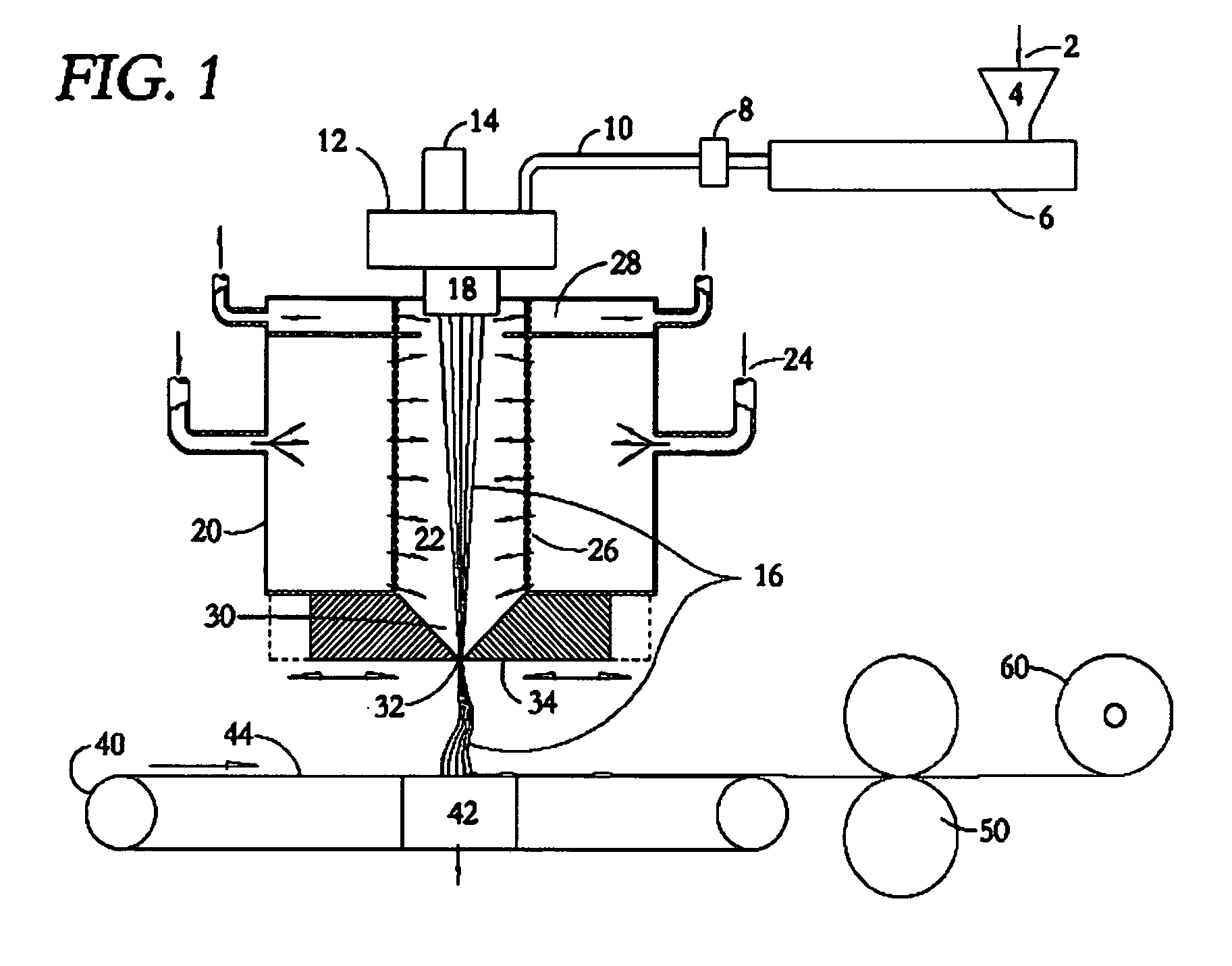
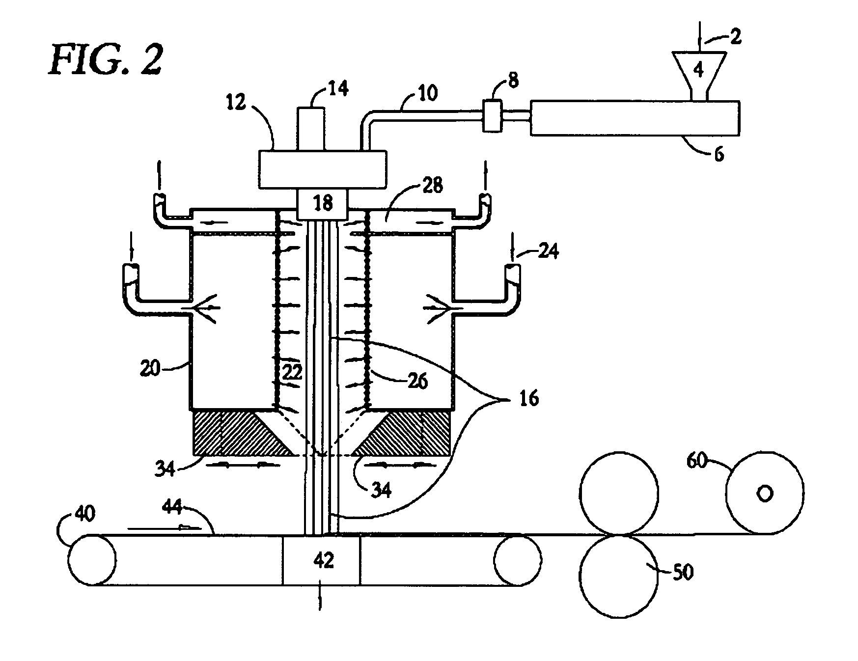
[0009] In contrast to the prior art systems described above, the system and method of the present invention involve an initial quench chamber and the use of a continuous two-dimensional slot across the entire machine width which produces a linear plane of filaments in the slot impingement point section. The linear plane of filaments has substantially constant filament distribution across the machine width, and provides for good control of cross-machine uniformity. As used throughout this description, “machine widths” refers to a dimension corresponding to the width generally of the spinning plate and is perpendicular to the collector belt travel. It is preferred that the width correspond to the desired end web width. The width of the machine is only limited by the ability to machine and maintain close geometric tolerance of the impingement slot dimensions. The process equipment is very simple compared to both eductive and non-eductive systems.
[0010] No air is educted into this system as the quench fluid, usually air, undergoes uniform acceleration into the impingement slot where the drawing force is developed. The same air is used for two purposes: first to quench the filaments and then to draw them as the air exits through the drawing impingement slot at high velocity. The drawing chamber is relatively small and there is substantially no nozzle length parallel to the fiber / air stream; therefore higher quench pressures can be obtained without leading to structural deflection problems that affect spinning area geometric tolerances which in turn would cause variations in spin velocities and turbulence. Higher pressures and the mixing effect of the exiting fiber / quench stream produce very high air and fiber velocities. The small amount of close tolerance machined surface area that is exposed to the fiber stream (i.e., only the tips of the air knives) collect far less dirt, polymer drippings and monomer build up than other systems. Cleaning is much simpler and only takes a few seconds while the machine is running by opening the slot for a few seconds and wiping clean the knife edges. An automatic wiper could be employed. This can be done several times a day, if needed, whereas most other conventional systems require hours and even days to clean educator and nozzle surfaces.
[0011] By selecting a suitable slot gap opening, the necessary drawing tension can be obtained. Filament cooling is controlled by regulating the temperature of the quench fluid and controlling the rate of flow of air past the filaments to exhaust ports near the top of the quench chamber, as is known in the prior art. The amount of quench air exiting the duct is important to the operation of the process, so this flow rate is preferably closely monitored and controlled. If there is too high an exhaust flow, the velocity of the air through the filament bundle will cause the filaments to waver and stick to each other, thereby causing filament breakage. The filaments will also be cooled too rapidly and large denier, brittle filaments will be produced. With too little exhaust, the filaments may not be totally quenched when they enter the drawing impingement slot, increasing the incidence of sticking to the slot's air knives.

Problems solved by technology

The width of the machine is only limited by the ability to machine and maintain close geometric tolerance of the impingement slot dimensions.
Higher pressures and the mixing effect of the exiting fiber / quench stream produce very high air and fiber velocities.
If there is too high an exhaust flow, the velocity of the air through the filament bundle will cause the filaments to waver and stick to each other, thereby causing filament breakage.
The filaments will also be cooled too rapidly and large denier, brittle filaments will be produced.
With too little exhaust, the filaments may not be totally quenched when they enter the drawing impingement slot, increasing the incidence of sticking to the slot's air knives.

Method used


Image

  • Method and apparatus for forming melt spun nonwoven webs
  • Method and apparatus for forming melt spun nonwoven webs
  • Method and apparatus for forming melt spun nonwoven webs

Examples


Embodiment Construction

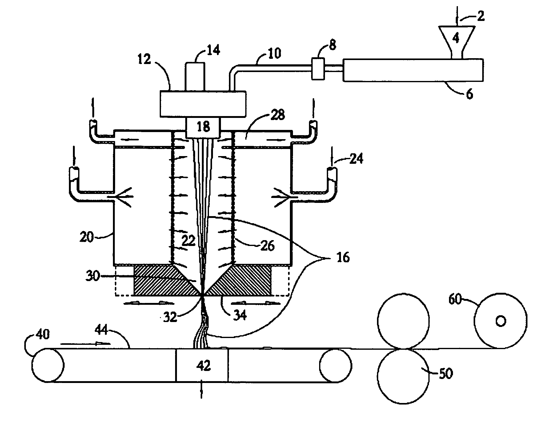
[0017] The following detailed explanations of FIGS. 1 and 2 of the preferred embodiments reveal the methods and apparatus of the present invention. The architecture depicted in the drawings is a conceptual diagram illustrating major functional units, and does not necessarily illustrate physical relationships.

[0018] The present invention harnesses the positive aspects of both eductive and non-eductive (and hybrid) systems into a more efficient and simpler design. More importantly, the invention solves many of the problems associated with conventional nonwoven spun bond systems including: spinning speed limitations, energy consumption, machine element cleanliness (i.e., hygiene), web uniformity, capital costs and process control. The invention also incorporates aspects of another, different type of nonwoven web forming technology, the meltblown process, as shown in U.S. Pat. No. 3,825,380 (Harding et al.) to help improve web formation control.

[0019] While the invention is described ...


PUM

PropertyMeasurementUnit
Pressureaaaaaaaaaa
Angleaaaaaaaaaa
Lengthaaaaaaaaaa

Abstract

A method and apparatus for forming nonwoven melt spun webs by spinning a curtain of filaments into a pressurized chamber where they are contacted with pressurized quenching fluid, then using the fluid to draw the filaments through a slot at the bottom of the chamber. The slot is a narrow two dimensional impingement point running the length of the filament curtain where the pressurized quench fluid passes through, escaping to atmosphere. The fluid pressure (potential) energy in the chamber is exchanged for velocity (kinetic) energy at the slot impingement point. The fast moving stream of fluid inside and exiting the slot acts to pull, or draw the filaments through the slot. The fluid and fiber stream is deposited onto a porous collection conveyor belt, forming a fleece web. The invention is more efficient, less complicated, easier to maintain and easier to control than prior systems for melt spinning nonwoven webs.

Description

CROSS REFERENCE TO RELATED APPLICATION [0001] This application claims priority from U.S. Provisional Patent Application Ser. No. 60 / 596311, filed Sep. 14, 2005 and entitled “Method and Apparatus For Forming A melt Spun Nonwoven Web”. The disclosure of this provisional patent application is incorporated herein by reference in its entirety.FIELD OF THE INVENTION [0002] The present invention pertains to methods and apparatus for spinning thermoplastic polymer filaments and, more particularly, to improvements therein using non-eductive drawing. BACKGROUND [0003] In general, spun bond nonwoven production machines can be classified as eductive “open” spinning systems and non-eductive “closed” spinning systems. Conventional broad loom eductive systems can generally trace their roots to the subject matter disclosed in U.S. Pat. No. 3,802,817 (Matsuki et al.) which describes a system that extrudes a curtain of filaments, extending the full width of the machine into, atmosphere (and / or imping...

Claims


Application Information

Patent Timeline
IPC IPC(8): D01D5/092B29C48/335B29C48/05D01G99/00
CPCB29C47/0014B29C47/20D04H3/005D01D5/092D01D5/0985B29C47/30B29C48/05B29C48/32B29C48/345
Inventor HARTGE, PERRY
Owner HARTGE HILLS DEV
Learn More