
Method and apparatus for a fully digital quadrature modulator

a quadrature modulator and fully digital technology, applied in the field of data communication, can solve the problems of not being able to accept the fabrication cost of mask adders for rf/analog circuits, not offering analog extensions, etc., and achieve the effect of maximising the reuse of hardwar

Active Publication Date: 2006-12-28
TEXAS INSTR INC
View PDF2 Cites 253 Cited by
  • Summary
  • Abstract
  • Description
  • Claims
  • Application Information

AI Technical Summary

Benefits of technology

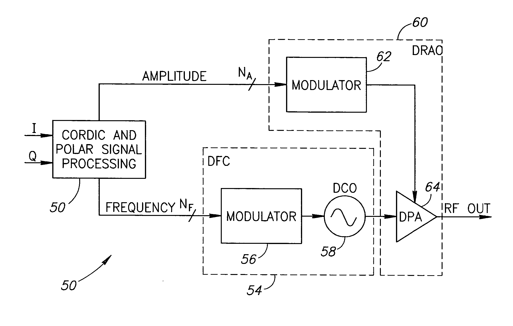
The present invention provides a method and apparatus for an RF transmitter that incorporates a complex RF modulator for complex RF modulation. The complex modulator is a fully digital system that can address virtually all possible modulation schemes. It can be used in a single chip CMOS based software defined radio (SDR) and is ideal for addressing multiple radio standards with a single hardware configuration. The complex modulator is also easier to design and manufacture than traditional analog quadrature architectures and offers advantages such as simplified compensation mechanisms, reduced noise levels, and simplified adaptation to multiple standards. The complex modulator is also more efficient in terms of bandwidth utilization and offers spectral relief at far-out frequencies.

Problems solved by technology

Currently, the DBB and AP designs invariably migrate to the most advanced deep-submicron digital CMOS process available, which usually does not offer any analog extensions and has very limited voltage headroom.
Design flow and circuit techniques of contemporary transceivers for multi-GHz cellular applications are typically analog intensive and utilize process technologies that are incompatible with DBB and AP processors.
The use of low-voltage deep-submicron CMOS processes allows for an unprecedented degree of scaling and integration in digital circuitry, but complicates implementation of traditional RF circuits.
Furthermore, any mask adders for RF / analog circuits are not acceptable from fabrication cost standpoint.
A problem arises, however, in that the amplitude and phase modulation paths have entirely different modulators and these two paths must be well aligned in their timing.
Even slight misalignment could result in intolerable distortion of the output modulated RF signal.
A disadvantage of this scheme, however, is in its difficulty to achieve high resolution compared to the polar scheme.
Additionally, amplitude and phase mismatches of the I and Q paths result in modulation distortion.
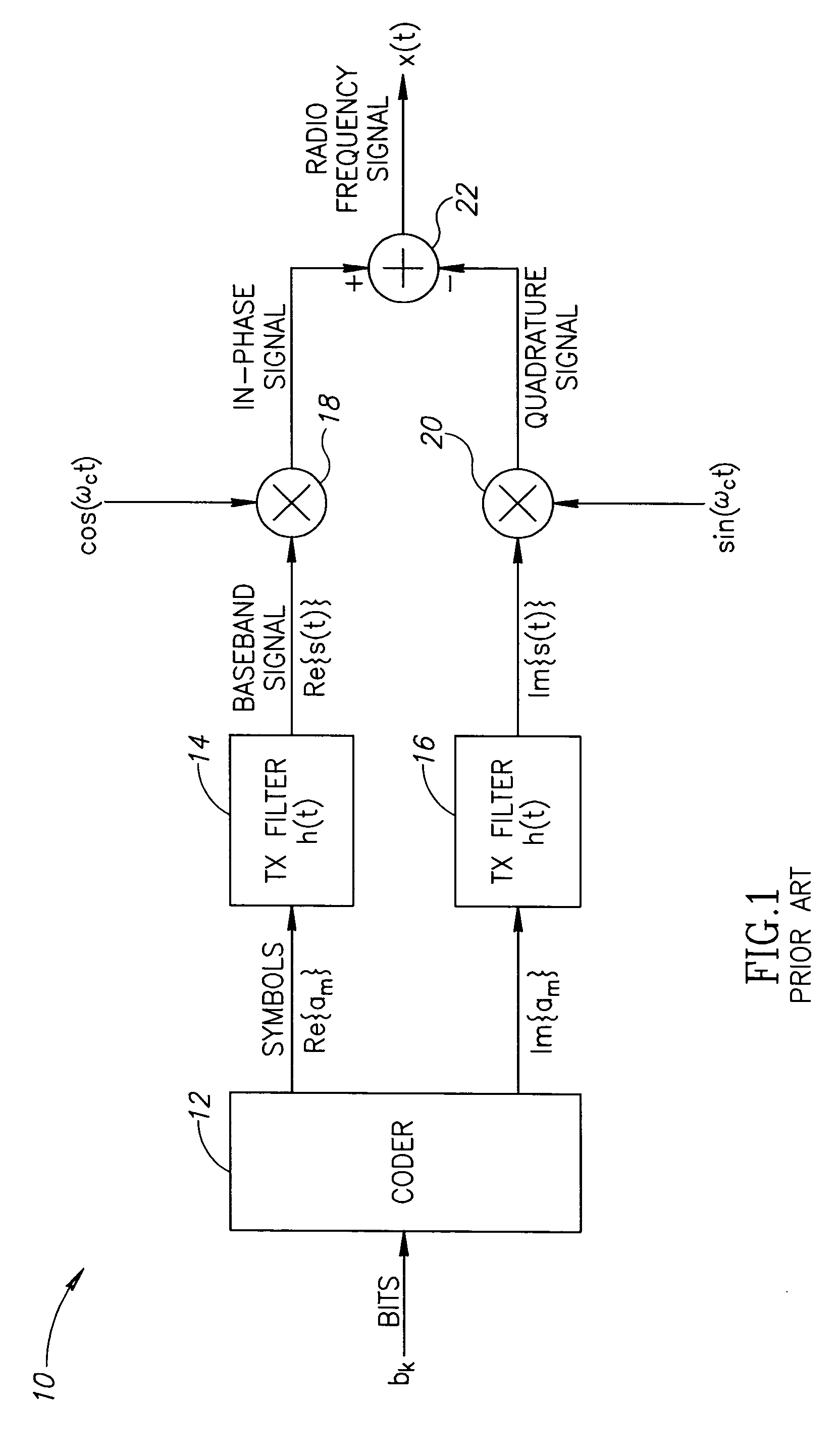
Analog Cartesian modulators (1) require analog intensive compensation mechanisms to minimize the impact of modulator impairments, such as I / Q gain imbalance and phase orthogonality error, (2) may require a surface acoustic wave (SAW) filter in the transmit path, which adds considerable cost and silicon area, to reduce noise levels of traditional analog circuitry, (3) make adaptation difficult to different radio standards due to the analog nature of the modulator.
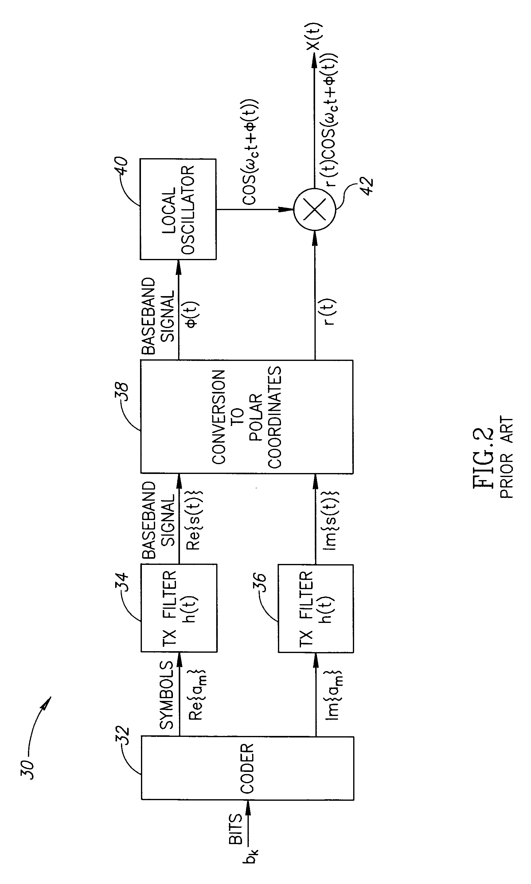
Prior art polar architectures also have several disadvantages, including (1) requiring wideband frequency modulation of the all digital phase locked loop (ADPLL), thereby complicating the varactor banks and associated control circuitry required by such architectures, (2) requiring a calibration procedure to determine and normalize the gain of the digitally controlled oscillator (DCO), whose accuracy is crucial and somewhat problematic in wideband modulation, (3) requiring accurate and problematic time-alignment tuning between the amplitude and phase modulating signals, in particular when the amplitude modulation is analog, (4) requiring a high-speed COordinate Rotation DIgital Computer (CORDIC) mechanism used to convert from Cartesian to polar, (5) having wider spectral replicas where the bandwidth of the spectral replicas is equivalent to that of the envelope signal rather than to the narrower bandwidth of the quadrature components I and Q, and (6) limited capability for carrier leakage cancellation.

Method used


Image

  • Method and apparatus for a fully digital quadrature modulator
  • Method and apparatus for a fully digital quadrature modulator
  • Method and apparatus for a fully digital quadrature modulator

Examples


Embodiment Construction

Notation Used Throughout

[0053] The following notation is used throughout this document.

TermDefinitionACWAmplitude Control WordADPLLAll Digital Phase Locked LoopAMAmplitude ModulationAPApplication ProcessorASICApplication Specific Integrated CircuitCMOSComplementary Metal Oxide SemiconductorCORDICCOordinate Rotation DIgital ComputerCUControl UnitDACDigital to Analog ConverterDBBDigital BasebandDCDirect CurrentDCODigital Controlled OscillatorDFCDigital to Frequency ConversionDPADigital Power AmplifierDQMDigital Quadrature ModulatorDRACDigital to RF Amplitude ConverterDRPDigital RF Processor or Digital Radio ProcessorDSPDigital Signal ProcessorECLEmitter Coupled LogicEDGEEnhanced Data rates for Global EvolutionFETField Effect TransistorFPGAField Programmable Gate ArrayGPSGlobal Positioning SystemGSMGlobal System for Mobile CommunicationHDLHardware Description LanguageICIntegrated CircuitLANLocal Area NetworkLOLocal OscillatorMOSMetal Oxide SemiconductorMP3MPEG Audio Layer 3MPEGMovin...


PUM


Abstract

A novel apparatus and method for a fully digital quadrature architecture for a complex modulator. The complex modulator can substitute for existing prior art analog quadrature modulator structures and those based on a digital polar architecture (r, θ). The modulator effectively operates as a complex digital-to-analog converter where the digital inputs are given in Cartesian form, namely I and Q representing the complex number I+jQ, while the output is a modulated RF signal having a corresponding amplitude and phase shift. The phase shift being with respect to a reference phase dictated by the local oscillator, which is also input to the converter / modulator. Several embodiments are provided including modulators incorporating dual I and Q transistor arrays, a single shared I / Q transistor array, modulators with single ended and differential outputs and modulators with single and dual polarity clock and I / Q data signals.

Description

REFERENCE TO RELATED APPLICATION [0001] This application claims priority to U.S. Provisional Application Ser. No. 60 / 601,587, filed Aug. 12, 2004, entitled “Method and Apparatus for a Fully Digital RF Transmitter”, incorporated herein by reference in its entirety.FIELD OF THE INVENTION [0002] The present invention relates to the field of data communications and more particularly relates to a method and apparatus for an RF transmitter incorporating a fully digital quadrature modulator. BACKGROUND OF THE INVENTION [0003] The cellular phone industry continues to thrive by providing support for Bluetooth personal area networking, positioning technology based on GPS and wireless LAN for high-speed local-area data access. Sophisticated applications, such as MP3 audio playback, camera functions, MPEG video and digital TV further entice a new wave of handset replacements. Such application support dictates a high level of memory integration together with large digital signal processing horse...

Claims


Application Information

Patent Timeline
Patent Type & Authority Applications(United States)
IPC IPC(8): H04L27/12
CPCH03C3/40H03C5/00H03F3/24H03F2200/324H04L27/365H03F2200/336H04K1/02H04L27/04H04L27/2092H03F2200/331
Inventor ELIEZER, OREN E.CRUISE, FRANCIS P.STASZEWSKI, ROBERT B.MEHTA, JAIMIN
Owner TEXAS INSTR INC
Learn More