
Laminated ceramic capacitor

a technology of laminated ceramic capacitors and capacitors, applied in the direction of stacked capacitors, fixed capacitor details, fixed capacitors, etc., can solve the problems of poor insulation resistance, difficult to obtain sufficient insulation resistance, and few high resistance particle boundaries, so as to achieve the effect of enhancing electrostatic capacitance and insulation resistance and further reducing the deterioration of the dielectric layer

Active Publication Date: 2006-02-02
TDK CORPARATION
View PDF5 Cites 8 Cited by
  • Summary
  • Abstract
  • Description
  • Claims
  • Application Information

AI Technical Summary

Benefits of technology

[0008] It is therefore an object of the invention, which was conceived in view of the aforesaid prior art, to provide a laminated ceramic capacitor which, even if the dielectric layer is made thinner to obtain a high electrostatic capacitance, can still maintain sufficient insulation resistance.
[0016] The ceramic material contained in the high resistance layer preferably contains the same elements as the component elements of the ceramic material contained in the dielectric layer. In this case, a high resistance layer having better insulating properties than those of the dielectric layer is easily obtained.
[0017] In the laminated ceramic capacitor according to the present invention, the dielectric material preferably contains one or more elements selected from a group comprising Mn, Cr, Co, Fe, Cu, Ni, Mo and V, and / or a rare earth element. In a dielectric layer comprising a dielectric material containing these elements, the ceramic material has higher stability. Due to the dielectric material containing these elements, the decrease of insulation resistance arising from time-dependent deterioration of the ceramic material can also be suppressed.
[0018] In the case where the dielectric material contains the aforesaid elements, the dielectric material preferably contains the same elements as the predetermined elements contained in the high resistance layer, the blending ratio of these elements in the high resistance layer being higher than the blending ratio of the same elements in the dielectric material particles. In this case, a high resistance layer having far superior insulating properties to those of the dielectric layer can be obtained, and as a result, the insulation resistance of the laminated ceramic capacitor can be further enhanced.
[0022] Among the one or more elements selected from a group comprising Mn, Cr, Co, Fe, Cu, Ni, Mo and V, Mn is preferred, and as the rare earth element, Y is preferred. It is particularly preferred that the predetermined element contained in the high resistance layer is Mn and Y In this case, the electrostatic capacitance and insulation resistance can be further enhanced, and deterioration of the dielectric layer can be further reduced.

Problems solved by technology

However, even with a laminated ceramic capacitor having a dielectric layer containing a one layer-one particle structure as in the aforesaid prior art, it was still difficult to obtain sufficient insulation resistance.
When the Inventors carried out a detailed examination, they discovered that in the aforesaid prior art laminated ceramic capacitor, the poor insulation resistance was due to the following factors.
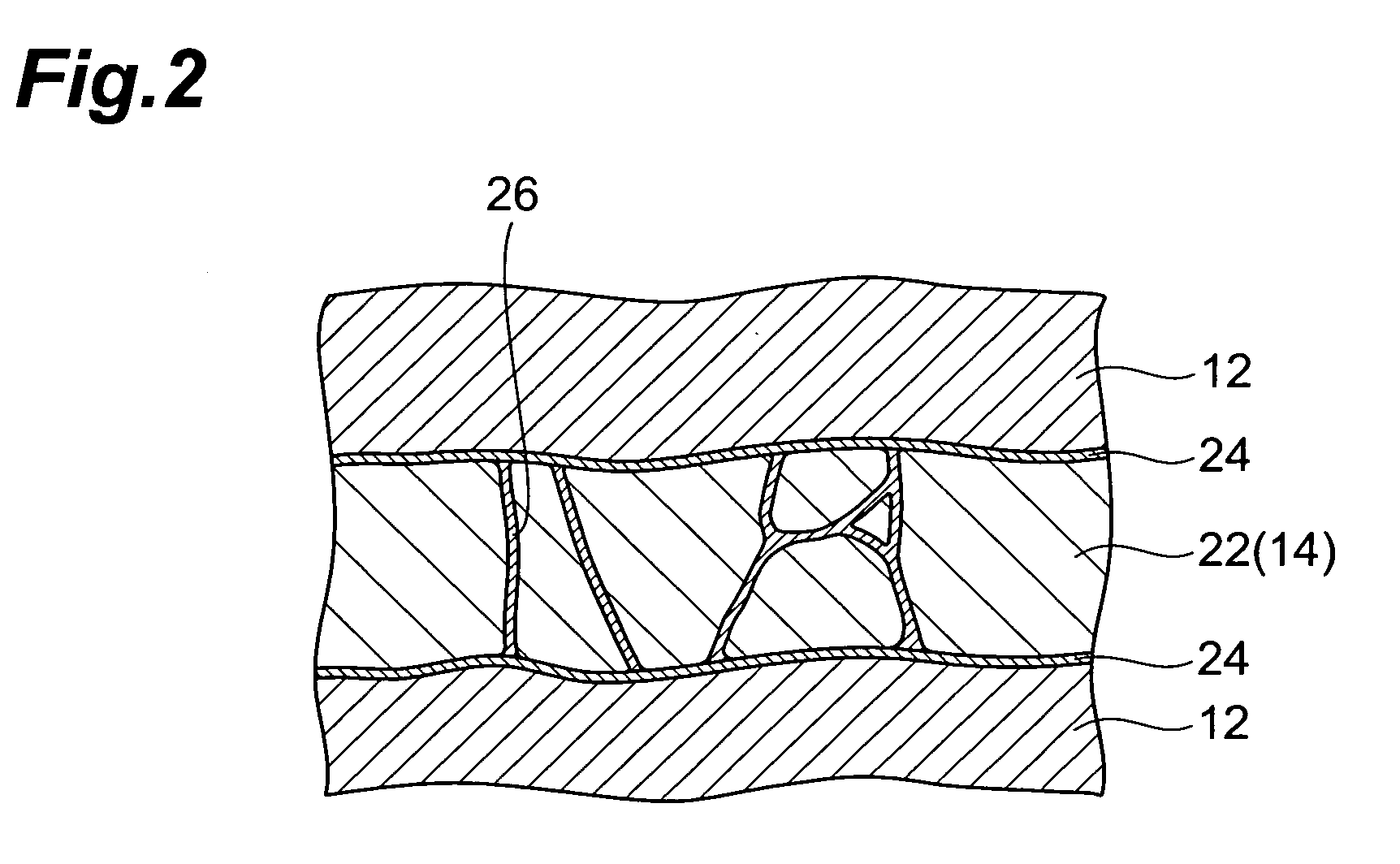
However, in a dielectric layer having the aforesaid one layer-one particle structure, there are very few high resistance particle boundaries.
Hence, in a laminated ceramic capacitor having a dielectric layer containing a one particle structure, insulating properties tend to be insufficient.

Method used


Image

  • Laminated ceramic capacitor
  • Laminated ceramic capacitor
  • Laminated ceramic capacitor

Examples


examples

[0051] The invention will now be described in more detail referring to specific examples, but it should be understood that the invention is not to be construed as being limited in any way thereby.

Manufacture of Laminated Ceramic Capacitor

[0052] First, BaTiO3, BaZrO3 and CaTiO3 were prepared as ceramic material starting materials, and MnCO3 and Y2O3 were prepared as metal element starting materials. These were wet-mixed by a ball mill, and temporarily sintered at 1000° C. for 3 hours. A binder, plasticizer, dispersion agent and solvent were then added to this temporarily sintered product to prepare a dielectric paste. At the same time, using Ni as an electrically conducting material, a binder, solvent, dispersion agent and plasticizer were added to prepare an internal electrode paste.

[0053] Next, this dielectric paste and internal electrode paste were alternately laminated, and the obtained laminated body was cut to a predetermined shape and size to obtain a green chip. Subsequen...


PUM

PropertyMeasurementUnit
mass ratioaaaaaaaaaa
thicknessaaaaaaaaaa
thicknessaaaaaaaaaa

Abstract

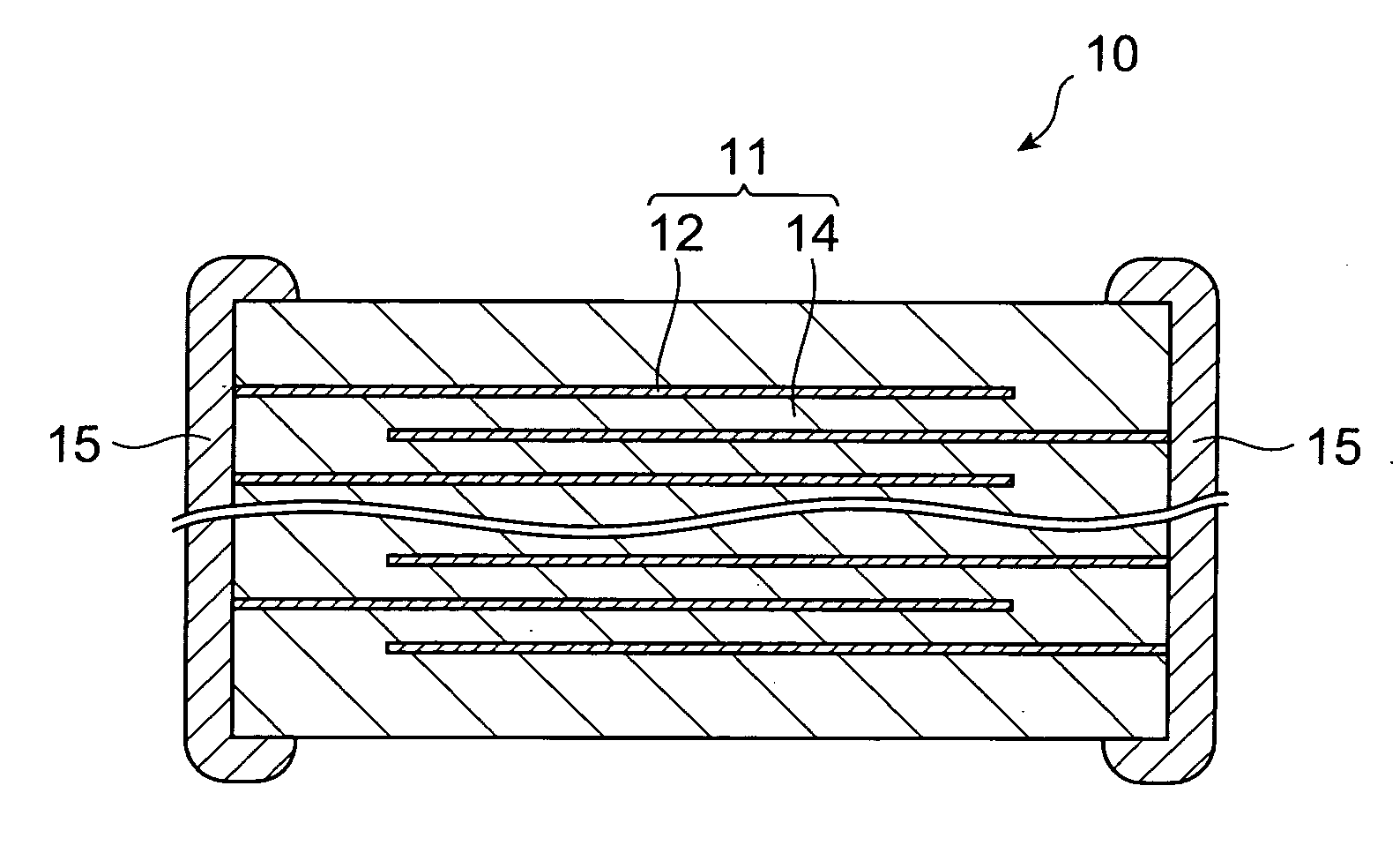
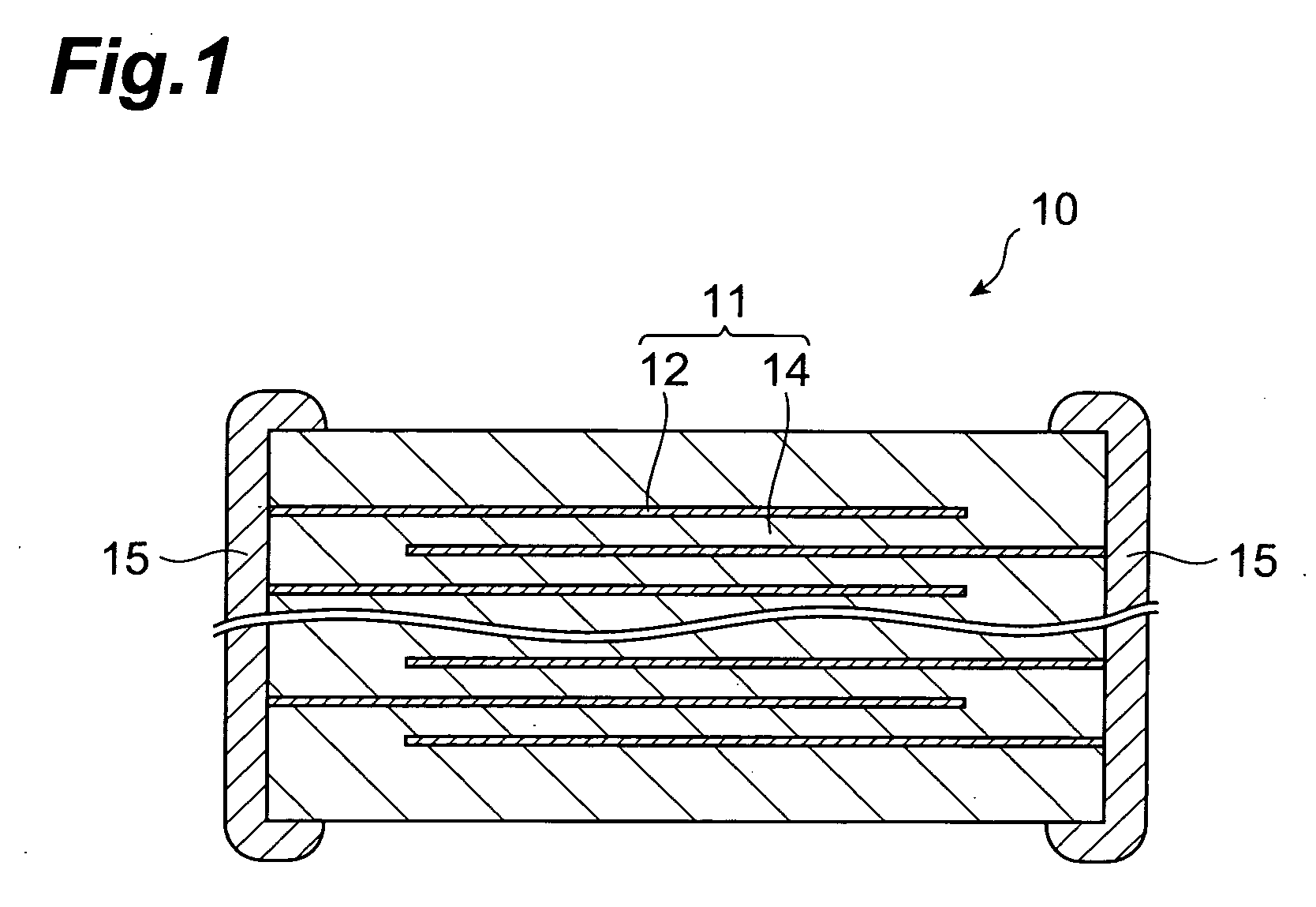
A capacitor 10 (laminated ceramic capacitor) according to the present invention comprises a capacitor body 11 wherein internal electrodes 12 and a dielectric layer 14 are alternately laminated, and external electrodes 15 are provided on the end faces thereof In this capacitor body 11, high resistance layers 24 are provided between the internal electrodes 12 and dielectric layer 14. These high resistance layers 24 contain a ceramic material, an element comprising at least one selected from a group comprising Mn, Cr, Co, Fe, Cu, Ni, Mo and V, and / or a rare earth element.

Description

BACKGROUND OF THE INVENTION [0001] 1. Field of the Invention [0002] The present invention relates to a laminated ceramic capacitor. [0003] 2. Related Background of the Invention [0004] In the prior art, a laminated ceramic capacitor has a structure where a dielectric layer of a ceramic material and an internal electrode are laminated alternately. In recent years, a demand has emerged for a small laminated ceramic capacitor having a large electrostatic capacitance. In order to satisfy this demand, in laminated ceramic capacitors, the dielectric layer is being made thinner, and the number of laminated layers is increasing. [0005] A laminated ceramic capacitor is required to have not only a large electrostatic capacitance, but also a high insulation resistance. However, since the insulation resistance is proportional to the thickness of the dielectric layer, when the dielectric layer was made thinner, although a large electrostatic capacitance was obtained, this insulation resistance t...

Claims


Application Information

Patent Timeline
Patent Type & Authority Applications(United States)
IPC IPC(8): H01G4/06
CPCH01G4/12H01G4/0085H01G4/30
Inventor IWANAGA, DAISUKE
Owner TDK CORPARATION
Learn More