Plasma display panel provided with electrode pairs bordering each sidewall of barrier ribs members

a technology of barrier ribs and electrode pairs, which is applied in the direction of electrodes, gas-filled discharge tubes, gas discharge vessels/containers, etc., can solve the problems of high discharge firing voltage, scan electrodes, and difficult to form sustain electrodes. , to achieve the effect of reducing the visible light transmittan

Inactive Publication Date: 2007-09-25
SAMSUNG SDI CO LTD
View PDF11 Cites 4 Cited by
  • Summary
  • Abstract
  • Description
  • Claims
  • Application Information

AI Technical Summary

Benefits of technology

[0009]An exemplary embodiment of a plasma display panel (PDP) according to the invention has advantages of high luminescence efficiency and easier fabrication by forming and disposing sustain electrodes and scan electrodes facing each other.
[0012]In one embodiment, the heights of the first electrode and the second electrode are less than half of a sum of the heights of the first barrier rib and of the second barrier rib. The heights of the first electrode and the second electrode may be less than or equal to 50 μm. With such a gap between the phosphor layer and the first and second electrodes, deterioration of the phosphor layer may be reduced.
[0014]Heights of the first and second electrodes may be greater than the widths thereof. Accordingly, the opposing discharge may become more easily facilitated. The width of the first electrode may be equal to the width of the second electrode, and the height of the first electrode can be equal to the height of the second electrode.
[0015]The height of the first electrode may be greater than the width thereof. The width of the second electrode can be greater than the width of the first electrode, and the height of the second electrode can be equal to the height of the first electrode. As the height of the second electrode is increased, a facing area between the second electrode and the address electrode is increased, and thereby address discharge may be generated more easily.
[0017]Additionally, a light-reflecting dielectric layer may be included between the first substrate and the address electrode. The light-reflecting dielectric layer may be formed from a dielectric material in a thin film or paste state. The light-reflecting dielectric layer effectively reflects visible light or vacuum ultraviolet (VUV) rays generated by the discharge cell, thereby improving luminescence efficiency.
[0019]The phosphor layer may be formed with a thickness of less than 10 μm, and thereby a decrease of visible light transmittance may be prevented.

Problems solved by technology

However, the opposing discharge type of PDP has disadvantages in that the discharge firing voltage is high and the fabrication of the PDP is difficult.
In other words, it is difficult to form sustain electrodes and scan electrodes so that they face each other within barrier ribs in a fabrication process of the opposing discharge type of PDP.
Additionally, in the case of a high definition PDP, it is more difficult to install sustain electrodes and scan electrodes within fine barrier ribs.

Method used


Image

  • Plasma display panel provided with electrode pairs bordering each sidewall of barrier ribs members
  • Plasma display panel provided with electrode pairs bordering each sidewall of barrier ribs members
  • Plasma display panel provided with electrode pairs bordering each sidewall of barrier ribs members

Examples


Embodiment Construction

[0025]Hereinafter, with reference to the accompanying drawings, embodiments of the present invention will be described in order for those skilled in the art to be able to implement it. As those skilled in the art would realize, the described embodiments may be modified in various different ways, all without departing from the spirit or scope of the present invention. Wherever possible, the same reference numbers will be used throughout the drawing(s) to refer to the same or like parts.

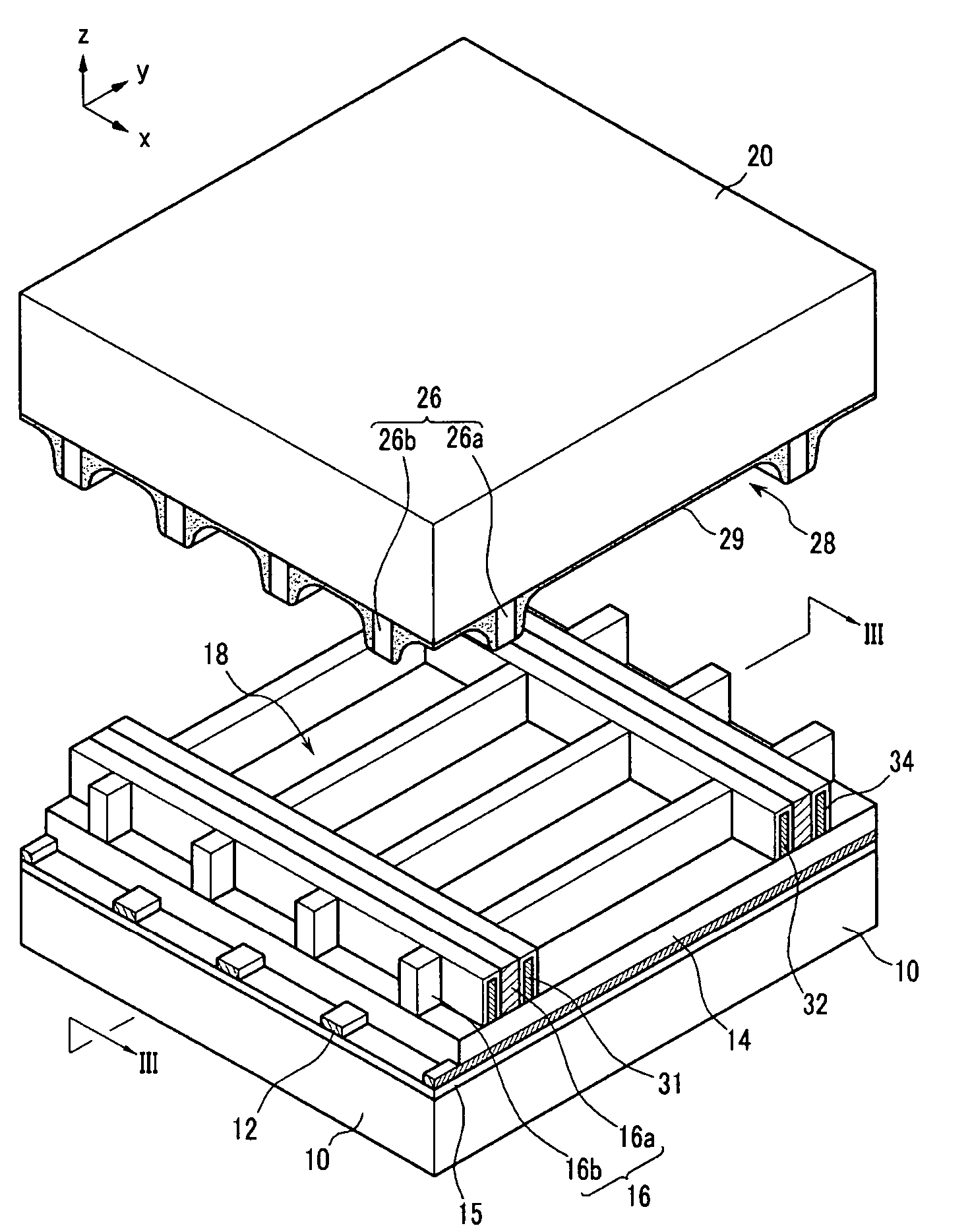
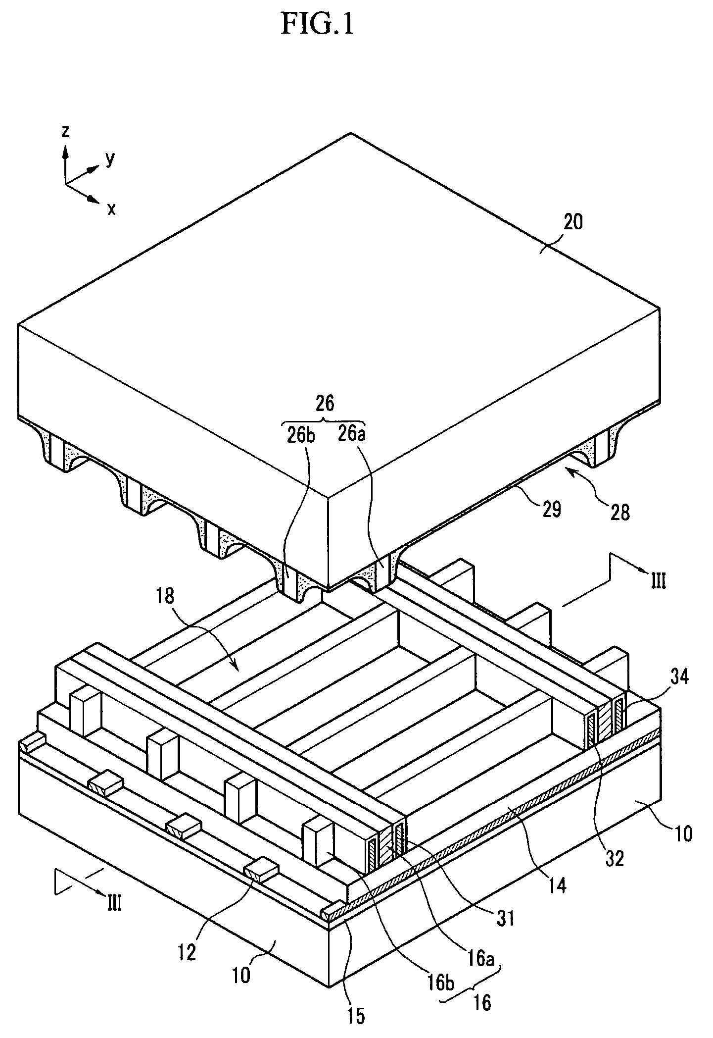
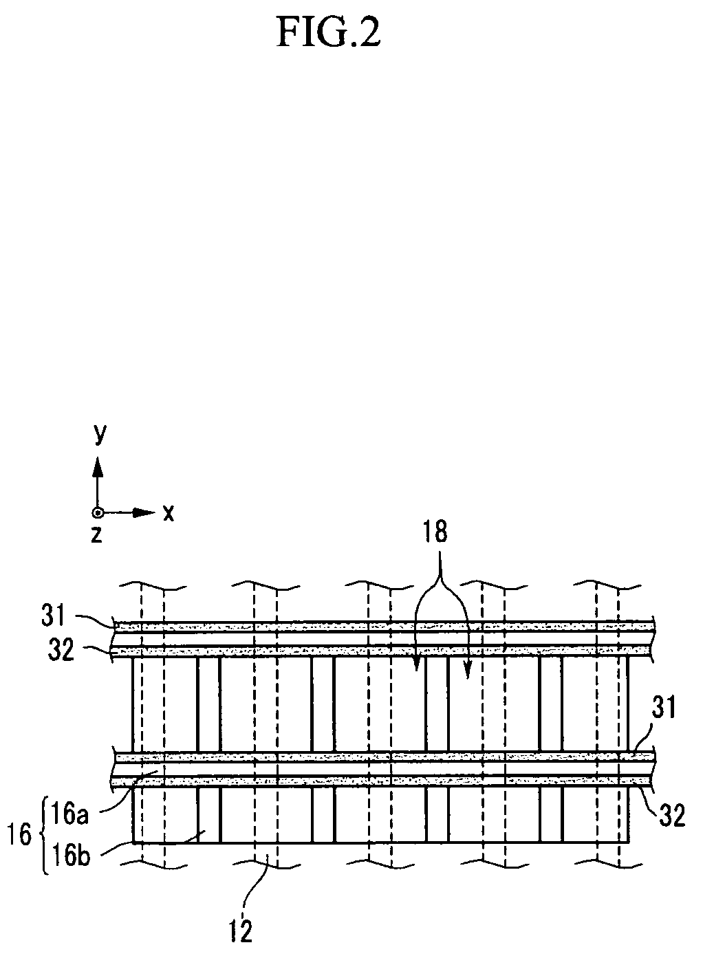
[0026]Referring to FIGS. 1-3, a PDP according to an exemplary embodiment of the present invention includes a rear substrate 10 and a front substrate 20, facing each other and having a space therebetween. Barrier ribs 16 and 26 are formed between the rear substrate 10 and the front substrate 20, and a plurality of discharge cells 18 and 28 forming discharge spaces are partitioned by the barrier ribs 16 and 26 between the two substrates 10 and 20.

[0027]A phosphor layer 29 is formed in the inner surface o...


PUM


Abstract

An exemplary PDP according to an embodiment of the present invention includes first and second substrates, an address electrode, first and second barrier ribs, first and second electrodes, and a phosphor layer. The first and second substrates face each other, the address electrode is formed on the first substrate and extends in a first direction, and the first barrier rib is formed on the first substrate and partitions a plurality of first discharge cells. The first and second electrodes extend along the second direction and are disposed in the first discharge cells. The second barrier rib is formed on the second substrate and partitions second discharge cells that correspond to the first discharge cells. The phosphor layer is formed in the discharge cells on the second substrate.

Description

CROSS-REFERENCE TO RELATED APPLICATION[0001]This application claims priority to and the benefit of Korean Patent Application 10-2004-0083463 filed in the Korean Intellectual Property Office on Oct. 19, 2004, the entire content of which is incorporated herein by reference.BACKGROUND OF THE INVENTION[0002](a) Field of the Invention[0003]The present invention relates to a plasma display panel. More particularly, the present invention relates to an opposing discharge type of plasma display panel having high luminescence efficiency and easier fabrication.[0004](b) Description of the Related Art[0005]A plasma display panel (hereinafter referred to as a “PDP”) is a display device for displaying an image with visible light generated by exciting phosphors with vacuum ultraviolet (VUV) rays radiated by plasma during gas discharge. A PDP provides a very wide screen of greater than 60 inches with a thickness of less than 10 cm. Additionally, a PDP has excellent color representation and exhibits...

Claims


Application Information

Patent Timeline
Patent Type & Authority Patents(United States)
IPC IPC(8): H01J17/49H01J11/12H01J11/14H01J11/16H01J11/22H01J11/24H01J11/26H01J11/32H01J11/34H01J11/36H01J11/38H01J11/42
CPCH01J11/16H01J11/24H01J11/36H01J2211/366H01J11/26
Inventor CHOI, HOON-YOUNGHUR, MIN
Owner SAMSUNG SDI CO LTD
Why Eureka
Try Eureka