Eureka AIR delivers breakthrough ideas for toughest innovation challenges, trusted by R&D personnel around the world.

Mechanical apparatus and method for dilating and delivering a therapeutic agent to a site of treatment

a technology of mechanical apparatus and therapeutic agent, applied in the direction of balloon catheter, immunological disorders, therapy, etc., can solve the problems of tissue ischemia and necrosis, traumatic open heart surgery, and failure to maintain patency, etc., and achieve the effect of precise sizing

Inactive Publication Date: 2005-02-24
BOSTON SCI SCIMED INC
View PDF19 Cites 69 Cited by
  • Summary
  • Abstract
  • Description
  • Claims
  • Application Information

AI Technical Summary

Benefits of technology

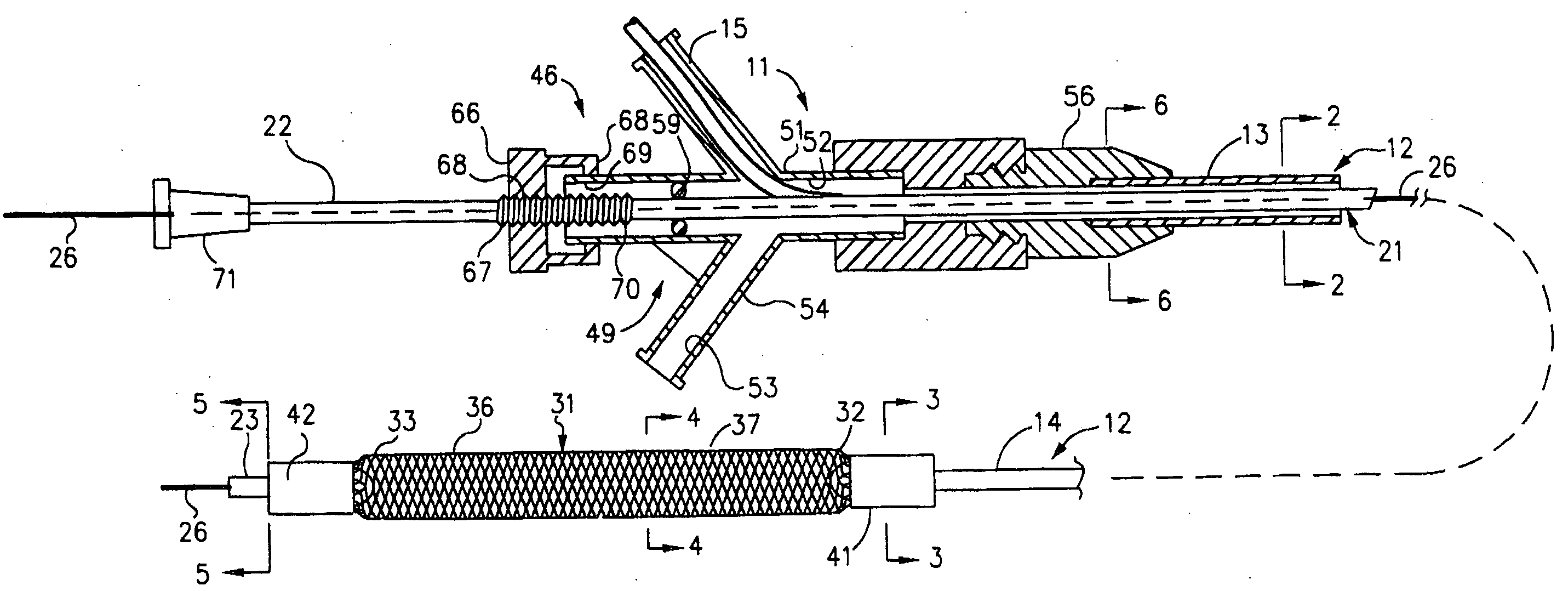
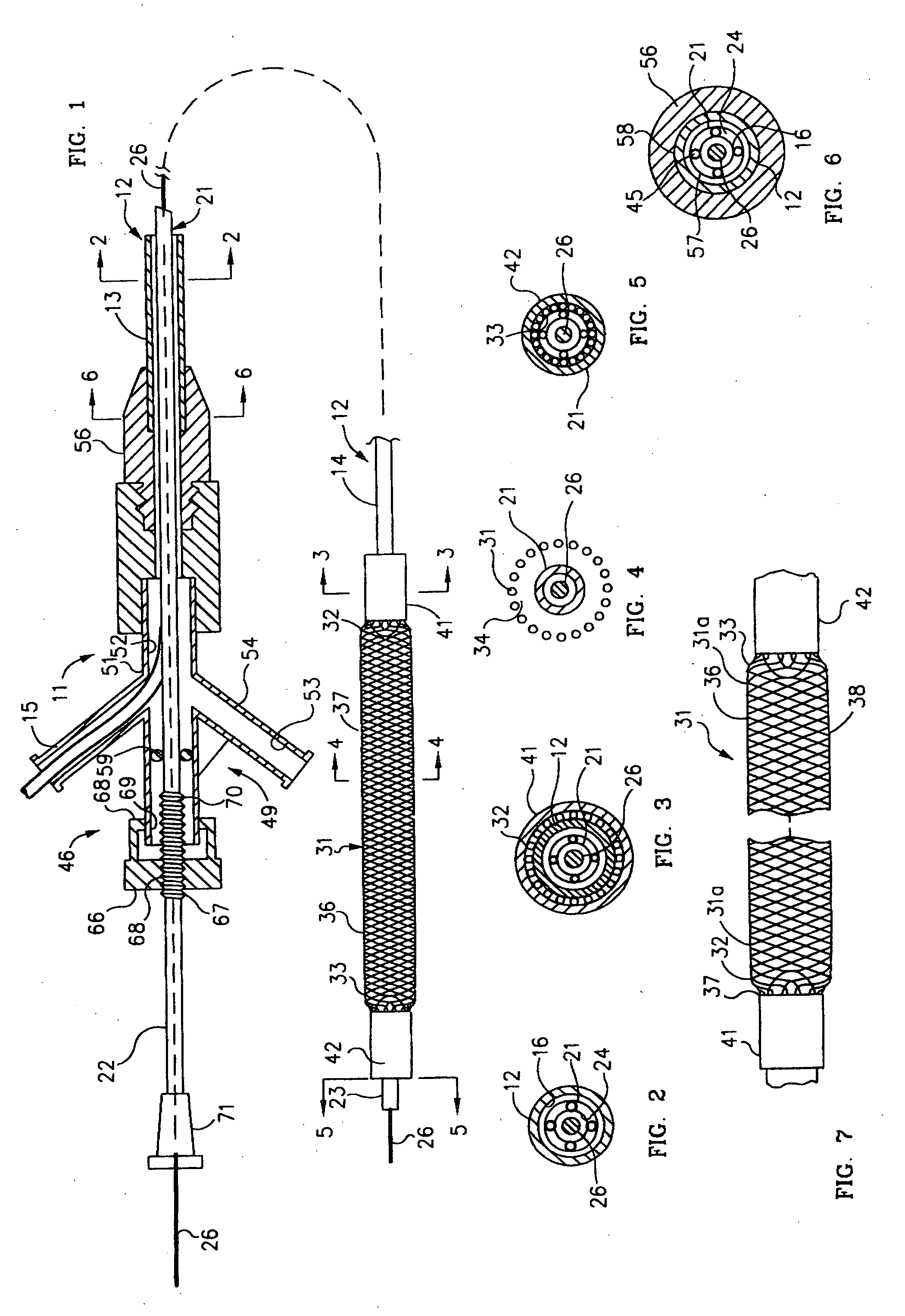
[0083] After a predetermine time, the electrical current can be altered to achieve another purpose or terminated. Since blood flows continuously through the dilatation and medicament delivery device 11 during the dilatation and medicament delivery procedure, there is minimal danger of ischemia occurring. This makes it possible to maintain dilatation and medicament delivery 11 of the obstruction over extended periods of time when desired. One particularly advantage for the mechanical dilatation and medicament delivery device 11 is that it could be used with patients which have obstructions of a critical nature that cannot even tolerate relatively short periods of balloon dilatation without leading to ischemia creating permanent damage or shock to the patient. Another advantage of the present invention is that uniform exposure of radiation to the vessel wall can be accomplished during this time.
[0084] The open construction of the expansion member 31 also serves to prevent blocking off of other vessels branching off from the vessel in the region in which dilatation and medicament delivery procedures are being performed because the blood can flow through the central interstices 38 of the expansion member 31.
[0085] After dilatation and medicament delivery of the lesion has been carried out for an appropriate length of time, the expansion member 31 can be moved from its expanded position to a contracted position by, for example, operation of the screw mechanism 46 in a reverse direction to cause separation of the distal extremities 14 and 23 to thereby cause elongation of the expansion member 31 with a concurrent reduction in diameter.
[0086] After the expansion member 31 has been reduced to its contracted or minimum diameter, the mechanical dilatation and medicament delivery device 11 can be removed along with the guide wire 26 after which the guiding catheter (not shown) can be removed and the puncture site leading to the femoral artery closed in a conventional manner.
[0087] Although, the procedure hereinbefore described was for treatment of a single stenosis, it should be appreciated that if desired during the same time that the mechanical dilatation and medicament delivery device 11 is within the guiding catheter, other vessels of the patient having stenoses therein can be treated in a similar manner merely by retracting the distal extremity of the mechanical dilatation and medicament delivery device 11 from the stenosis being treated, placing another prosthesis over the expansion member, and then advancing it into another stenosis in another vessel in a similar manner.
[0088] The advantages of using the present invention is to delivery a therapeutic agent or medicament to a vascular segment for prolonged periods while allowing continuous perfusion of blood into the distal to the treatment area.

Problems solved by technology

Diseased and obstructed coronary arteries can restrict the flow of blood and cause tissue ischemia and necrosis.
Open heart surgery is, of course, very traumatic for patients.
A recurrent problem with the previous devices and PTCA procedures is their failure to maintain patency due to the growth of injured vascular tissue.
Only limited quantities of therapeutic agents can be delivered because of “wash-out” of the drug into the circulation during balloon placement and due to the limited time the inflated balloon can be left in place due to ischemia caused by the balloon.
This method has the disadvantage of not have the capability to dilate the obstruction prior or concurrent to the delivery of a drug.
This method also has the inherent disadvantage that since the site of therapy is intravascular, most of the drug will be washed off or dissolved off the electrodes into the circulating blood stream before it is advanced through the vascular system from its percutaneous entry and to the distal site of treatment.
This again limits the amount of the drug delivered to the site and also potentially subjects the patient to harmful or toxic systemic exposure.
There is, however, some evidence that high pressure “jetting” of a drug solution out of small pores close to the vessel lumen can in fact cause vessel wall injury.
The development of double skinned, microporous (or weeping) balloons obviated this “jetting” effect to some extent, but diffusion of the drug into the vessel wall is still slow, and much of the drug can be lost through subsequent “washout effects”.
This method leads to limited amounts of drugs or therapeutics agents delivered to the tissues or cells.
Furthermore, in all of these methods the balloon must be expanded and thereby restricts blood flow to the distal arterial segments while the balloon is in the expanded configuration thus limiting the time the drug delivering balloon can be clinically utilized.
There are also several disadvantages using either a stent or balloon catheter to delivery a therapeutic agent or medicament to a vascular segment.
Balloon catheters employed to delivery a therapeutic agent or medicament to a vascular segment have limitations including potential balloon rupture and ischemia due to balloon inflation limiting distal blood flow to the artery.
This leads to tissue ischemia and potential necrosis.

Method used


Image

  • Mechanical apparatus and method for dilating and delivering a therapeutic agent to a site of treatment
  • Mechanical apparatus and method for dilating and delivering a therapeutic agent to a site of treatment
  • Mechanical apparatus and method for dilating and delivering a therapeutic agent to a site of treatment

Examples


example 2

Local Delivery of Paclitaxel

[0092] Paclitaxel is one of the most potent inhibitors of cellular proliferation in clinical use and has been shown to be efficacious in a large number of cancers. Paclitaxel is very lipophilic and essentially insoluble in water. Liposome or micelles were prepared by mixing 0.72 mg phosphatidylcholine and 0.8 mg of phosphatidylserine in a test tube with 800 microliters of chloroform. The solution was evaporated to dryness. Paclitaxel labeled with a fluorescent probe (Oregon Green) was dissolved in methanol to obtain a 20 1 mg / 1 ml solution. Twenty-five microliters of this solution was combined with 975 microliters of 8 mM CaCl2. The paclitaxel solution was added to the dried lipid mixture in small aliquots with constant stirring. The hydrogel-coated metal mesh catheter was placed in the paclitaxel / liposome or micelle mixture and then removed. In some cases, the hydrogel-coated mesh portion of the catheter is covered with a retractable sheath to prevent l...

example 3

In-vivo Delivery of a Charged Paclitaxel Analogue (TX-67)

[0093] Catheters loaded with a charged paclitaxel analog (TX-67) were created for In-vivo delivery. 75 mg of TX-67 were compounded into 2 g of a 5% polymer solution dissolved in an 85% Ethanol 15% water solution. The solution was vortex until the TX-67 was dissolved. Multiply coats of the resulting mix were applied directly to a metal mesh catheter and allowed to dry in a 40° C. oven.

[0094] The catheter was positioned at the target site of a study porcine animal and the mesh was expanded against it's arterial wall. Iontophoersis was performed by applying an electrical current to the catheter mesh. The circuit was completed by placing a conductive patch on the animal's skin that was connected to a current source. In this example the iontophoersis parameters were 10 mA for 10 minutes. The mesh was contracted and removed.

[0095] One hour post procedure the tissue was excised and placed on dry ice. The frozen tissue samples were...

example 4

Time Dependent In-vivo Studies with a Charged Paclitaxel Analogue (TX-67)

[0097] Several present invention catheters were used to treat four porcine femoral arteries. The catheters were coated with TX-67 incorporated in a hydrogel non-therapeutic substrate. The catheters were advanced to the femoral arteries of each porcine animal and the mesh expanded to make contact with the arterial wall. A percutaneous patch was placed over the site and continuous DC current of 2 mamp was administered with the negative electrode attached to the catheter and positive to the skin. Continuous blood flow was established through the mesh and documented on cine-angiography. The mesh was left expanded for a total of ten minutes and then the electrical current was discontinued and the mesh contracted in diameter and removed. The animals were sacrificed two at one hour and the other two at twenty four hours after treatment and the femoral arteries at the site of treatment removed. The frozen tissue sampl...


PUM


Abstract

A mechanical dilatation and medicament delivery device for enlarging a flow passage of a vessel by dilating and delivering a charged paclitaxel analogue therapeutic agent or medicament to an obstruction in the vessel. The present invention comprises a substantially cylindrically shaped expansion member and includes a means engaged to the expansion member for altering the distance between the proximal end and the distal end of the expansion member thereby transforming the expansion member between a diametrically contracted configuration to diametrically expanded configuration. A charged paclitaxel analogue therapeutic agent or medicament is coated on either the expansion member, or combined / incorporated into a substrate coated on the expansion member. The present method comprises the steps of advancing the coated expansion member to the obstruction in a vessel and applying opposed forces on said expansion member in an axial direction to move the expansion member to an expanded configuration wherein the expansion member dilates the obstruction and the expansion member either passively or actively delivers a charged paclitaxel analogue therapeutic agent or medicament to the obstruction.

Description

PRIOR APPLICATIONS [0001] This application is a continuation-in-part of application Ser. No. 09 / 997,855 filed on Nov. 29, 2001.FIELD OF THE INVENTION [0002] In general, the present invention relates to percutaneous transluminal devices and methods that are used treat obstructed (sclerotic) vessel lumina in humans. In particular, this invention relates to a mechanical apparatus and method for dilating an obstruction within a vessel while simultaneously or subsequently delivering a specified therapeutic agent or medicament dose. The present invention permits a continuous flow of blood during the entire procedure, including the extended period that may be necessary to continue the delivery of the therapeutic agent or medicament to the obstruction. BACKGROUND OF THE INVENTION [0003] Cardiovascular disease is commonly accepted as being one of the most serious health risks facing our society today. Diseased and obstructed coronary arteries can restrict the flow of blood and cause tissue i...

Claims


Application Information

Patent Timeline
Patent Type & Authority Applications(United States)
IPC IPC(8): A61M25/10A61M29/00A61M29/02A61N1/30
CPCA61M29/02A61M2025/0004A61M2025/0008A61N1/306A61M2025/0183A61M2025/105A61M2025/0175A61P35/00A61P37/02A61P43/00A61P9/00
Inventor SEGAL, JEROMESCOTT, NEAL
Owner BOSTON SCI SCIMED INC
Why Eureka
Eureka Blog
Learn More