
Carrying device and exposure equipment

A technology of carrying device and carrying platform, which is applied in the direction of microlithography exposure equipment, photomechanical equipment, photolithography exposure device, etc., can solve the problem of inconsistent exposure degree of photoresist, improve device quality, and increase product yield , the effect of uniform exposure

Active Publication Date: 2017-05-31
CHONGQING BOE OPTOELECTRONICS +1
View PDF6 Cites 14 Cited by
  • Summary
  • Abstract
  • Description
  • Claims
  • Application Information

AI Technical Summary

Problems solved by technology

[0004] The present invention aims to solve at least one of the technical problems existing in the prior art, and proposes a carrying device and exposure equipment to improve the problem of inconsistent exposure of photoresist at different positions on the substrate

Method used


Image

  • Carrying device and exposure equipment
  • Carrying device and exposure equipment
  • Carrying device and exposure equipment

Examples


Embodiment Construction

[0031] Specific embodiments of the present invention will be described in detail below in conjunction with the accompanying drawings. It should be understood that the specific embodiments described here are only used to illustrate and explain the present invention, and are not intended to limit the present invention.

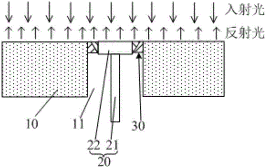
[0032] As an aspect of the present invention, a carrying device is provided, figure 2 and Figure 8 Two structural schematic diagrams of the carrying device are respectively. Such as figure 2 and Figure 8 As shown, the carrying device includes a carrying platform 10, and the carrying platform 10 is provided with a lifting passage 11 passing through the carrying platform 10, and a lifting structure 20 is arranged in the lifting passage 11, and there is a space between the lifting structure 20 and the inner wall of the lifting passage 11. interval. A light reflection compensating block 30 is also arranged between the lifting structure 20 and the inner wall...


PUM

PropertyMeasurementUnit
reflectanceaaaaaaaaaa
emissivityaaaaaaaaaa

Abstract

The invention provides a carrying device. The carrying device comprises a carrying table, wherein a lifting passage which penetrates through the carrying table is formed in the carrying table, a rising and falling structure is formed in the lifting passage, a gap exists between the rising and falling structure and the internal wall of the lifting passage, a light reflection compensating block is further arranged between the rising and falling structure and the internal wall of the lifting passage, and both the difference of light reflectivity of the top face of the light reflection compensating block and a load bearing face of the carrying table and the difference of light reflectivity of the top face of the light reflection compensating block and the top face of the rising and falling structure are not greater than preset threshold values. Correspondingly, the invention further provides exposure equipment. According to the carrying device and the exposure equipment, the degree of exposure of photoresists at different positions of a substrate can be more uniform.

Description

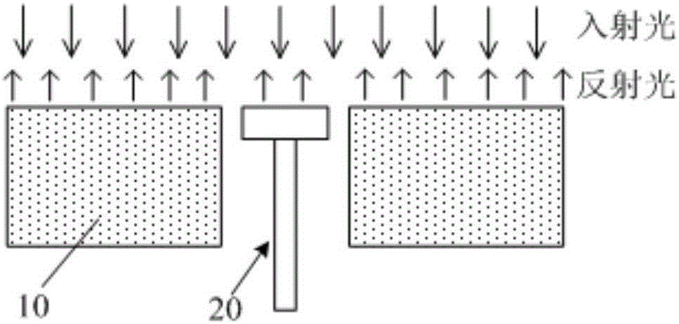
technical field [0001] The invention relates to the production field of display devices, in particular to a carrying device and exposure equipment. Background technique [0002] figure 1 It is a structural schematic diagram of a carrying device in an existing exposure equipment, which includes a carrying table 10 and a lifting structure 20 (such as a lifting rod or a lifting pin). During the exposure process, the lifting structure 20 is lowered, and the substrate is placed on the carrier platform 10; after the exposure, the lifting structure 20 is raised to lift the substrate, so that the substrate can be taken away easily. [0003] In the current carrying device, there is a certain gap between the lifting structure 20 and the carrying platform 10, resulting in inconsistent reflectivity between the gap area and the surface of the carrying platform 10. Therefore, in the exposure process, the exposure rate of the photoresist at different positions of the substrate is differen...

Claims


Application Information

Patent Timeline
Patent Type & Authority Applications(China)
IPC IPC(8): G03F7/20
CPCG03F7/70716G03F7/20G03F7/707G03F7/70791G03F7/70733G02F1/1303H01L27/1214
Inventor 陈启超周子卿韩乾浩
Owner CHONGQING BOE OPTOELECTRONICS
Learn More