Autofocus method and autofocus device

a technology of autofocus and method, which is applied in the direction of mountings, microscopes, instruments, etc., can solve the problems of low resolution of this type of color detector, and the inability to always guarantee the focusing of such a method

Inactive Publication Date: 2016-07-28
SAKURA FINETEK U S A
View PDF6 Cites 14 Cited by
  • Summary
  • Abstract
  • Description
  • Claims
  • Application Information

AI Technical Summary

Benefits of technology

The patent describes a technical solution for improving image quality in a microscope or optical system. It involves guiding two light paths in a symmetrical way around the optical axis, which allows the reflections of the sample to be analyzed separately. The separation of the light paths is important for detecting individual layers in a layer structure without overlapping reflections from adjacent layers. Additionally, the patent suggests using filters with different transmission values to amplify, lengthen or consolidate pixels, and improve uniform exposure of the image in all frequency ranges. It also mentions that a high damping filter area can be used to read out only every second pixel. Overall, the technical effects of the patent make it easier to get high-quality images in optical systems.

Problems solved by technology

Typically, however, when using high-resolution systems in the case of the described sample, the tolerances in the layer thickness (e.g., of the cover slip or of specimen slide) are greater than the depth of field of the imaging system and a focusing cannot always be guaranteed with such a method.
Because of the required four detector cells per pixel, the resolution of this type of a color detector is low.

Method used


Image

  • Autofocus method and autofocus device
  • Autofocus method and autofocus device
  • Autofocus method and autofocus device

Examples


Embodiment Construction

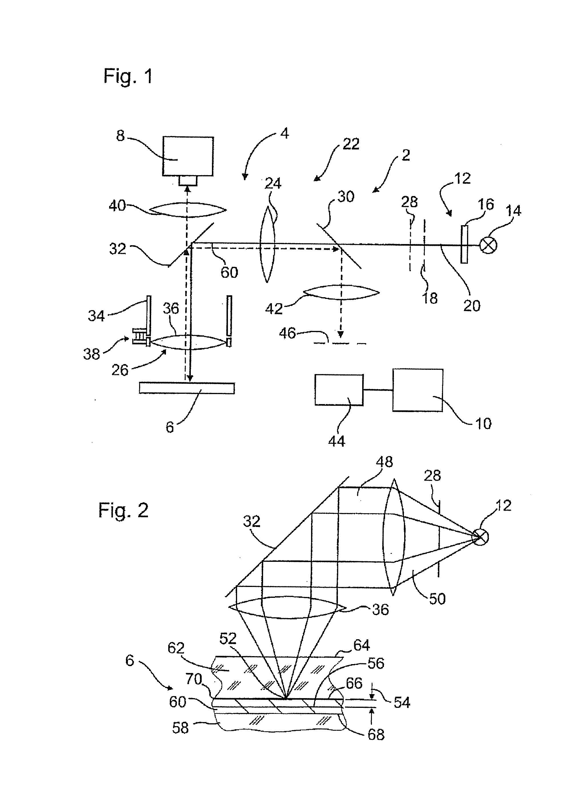
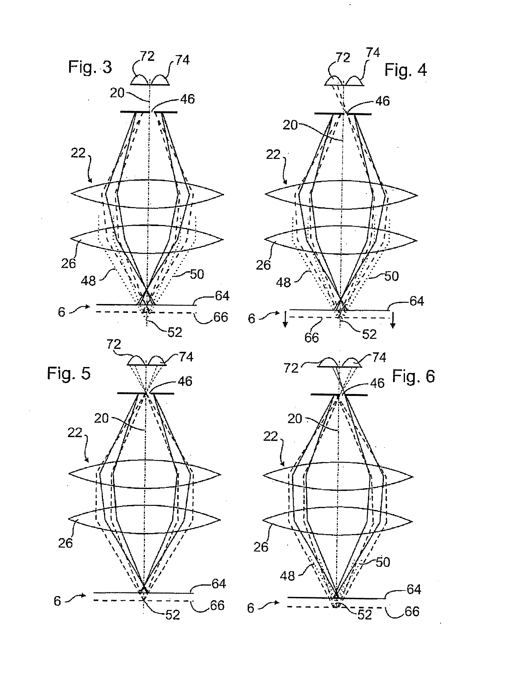
[0089]FIG. 1 depicts an autofocus device 2 which is integrated into an optical imaging system 4. The optical imaging system in this special embodiment is a microscope for fluorescence analysis of biological material in a sample 6. For this, the optical imaging system 4 includes an image detector 8 or a camera, which is connected to a control means 10 for acquisition control and saving of images taken, or an eyepiece for observing the sample directly. The control means 10 is part of both the optical imaging systems 4 as well as the autofocus device 2 and is used to control the autofocus methods described in the following.

[0090]The autofocus device 2 includes a light source 12, which makes light available for the autofocus method. It may also provide the light for the fluorescence analysis, wherein, as a rule, it is more expedient for the optical imaging system 4 to have another light source (not shown) for this. The light source 12 has a light generator 14, e.g., a LED (light emittin...


PUM

PropertyMeasurementUnit
widthaaaaaaaaaa
distanceaaaaaaaaaa

Abstract

The invention is based on an autofocus method in which light from a light source is focused at a measurement light focus in a sample and is reflected from there and the reflected light is guided through an optical system in two light paths onto at least two detector elements. In order to achieve fast and accurate automatic focusing on the sample, it is proposed that the measurement light focus is moved in layers of the sample which reflect light to different extents, and the detector elements are arranged in such a way that, in this case, profiles of a radiation property registered by the detector elements are different and a focus position is set in a manner dependent on the profiles.

Description

CROSS-REFERENCE TO RELATED APPLICATION[0001]The application is a divisional of co-pending U.S. patent application Ser. No. 13 / 255,827, filed Sep. 9, 2011, which claims benefit from U.S. National Phase application under 35 U.S.C. §371 of International Application No. PCT / IB2010 / 000518, filed Mar. 11, 2010, entitled AUTOFOCUS METHOD AND AUTOFOCUS DEVICE and incorporated herein by reference.[0002]The application relates to an autofocus method, in which light from a light source is focused at a measurement light focus in a sample and is reflected from there and the reflected light is guided through an optical system and at least one aperture in two light paths onto at least two detector elements.PRIOR ART[0003]Two methods are known for automatically focusing microscopes at a sample:[0004]The position of a sample or the distance of the sample from a reference point is measured, in that light reflected from the sample is examined interferometrically for patterns, intensity or the like.[00...

Claims


Application Information

Patent Timeline
Patent Type & Authority Applications(United States)
IPC IPC(8): G02B21/36G02B21/08G02B21/18G02B7/09
CPCG02B21/365G02B21/18G02B21/08G02B7/09G02B21/247
Inventor HING, PAULHENSLER, SVEN
Owner SAKURA FINETEK U S A
Why Eureka
Try Eureka