Systems and methods for localizing and analyzing samples on a bio-sensor chip

Inactive Publication Date: 2003-01-16
OTILLAR ROBERT P +1
View PDF18 Cites 269 Cited by
  • Summary
  • Abstract
  • Description
  • Claims
  • Application Information

AI Technical Summary

Benefits of technology

[0016] The present invention advantageously provides a user with the ability to quickly and efficiently custom design an "experiment" as opposed to using a ready-to-use product which is generally very difficult to modify. The present invention provides an easy-to-
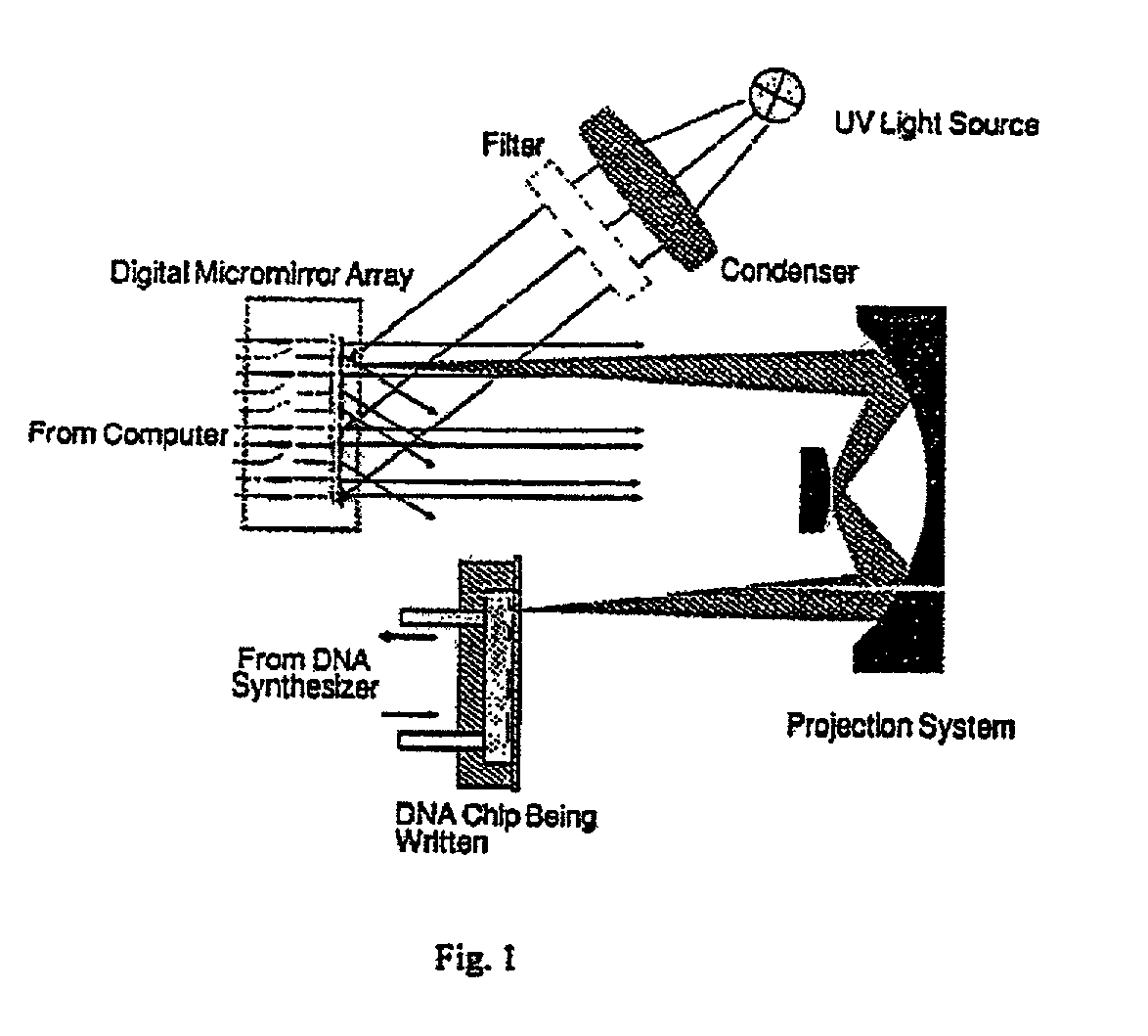
handle platform, which may be used repeatedly and may be prepared in-house. Consequently, the present invention is not limited to the surface deposits as are the devices described above (see, e.g., FIG. 1), but allows sample preparation either by surface deposition (e.g., at the bottom or at the walls of a crater) or by utilizing liquid state reactions allowing reagent contained in the liquid trapped within each well by a cap to mix with reagents contained in the liquid above the craters by opening the "lids" (caps) at will.
[0039] The present invention provides platforms useful for performing a variety of biological and chemical assays. In one embodiment of the present invention a substrate is provided with one or a plurality of wells or craters formed in the substrate. Individually controllable lids are provided in some embodiments to allow for contained environments within each crater or well. Such devices are intended to be used in a fluid medium, for example, submerged in a liquid, covered by a gel, or introduced to air or other gaseous environment. By controlling the lids, each enclosed crater volume becomes separated from the surrounding environment. Any materials, e.g., fluid medium within the crater, particles suspended therein, and / or material that adheres to an enclosed crater's inner surface, are not affected by subsequent changes that occur in the surrounding environment while the lid is closed. Such changes include presenting different chemical compositions to the surrounding fluid medium, irradiating the device or individual craters, or providing solid materials in the surrounding medium. A lid may or may not be completely liquid-tight, but mixing of the medium outside an enclosed well with the medium contained inside a well will be dramatically slowed. Hence, each lid provides an effective means to separate materials, e.g., solids and / or liquids, in the interior of the well from materials outside the enclosed well. In this manner, different wells can be populated with controlled amounts of different substances, e.g., different chemical species, by selectively opening and closing wells as changes are made to the surrounding environment.
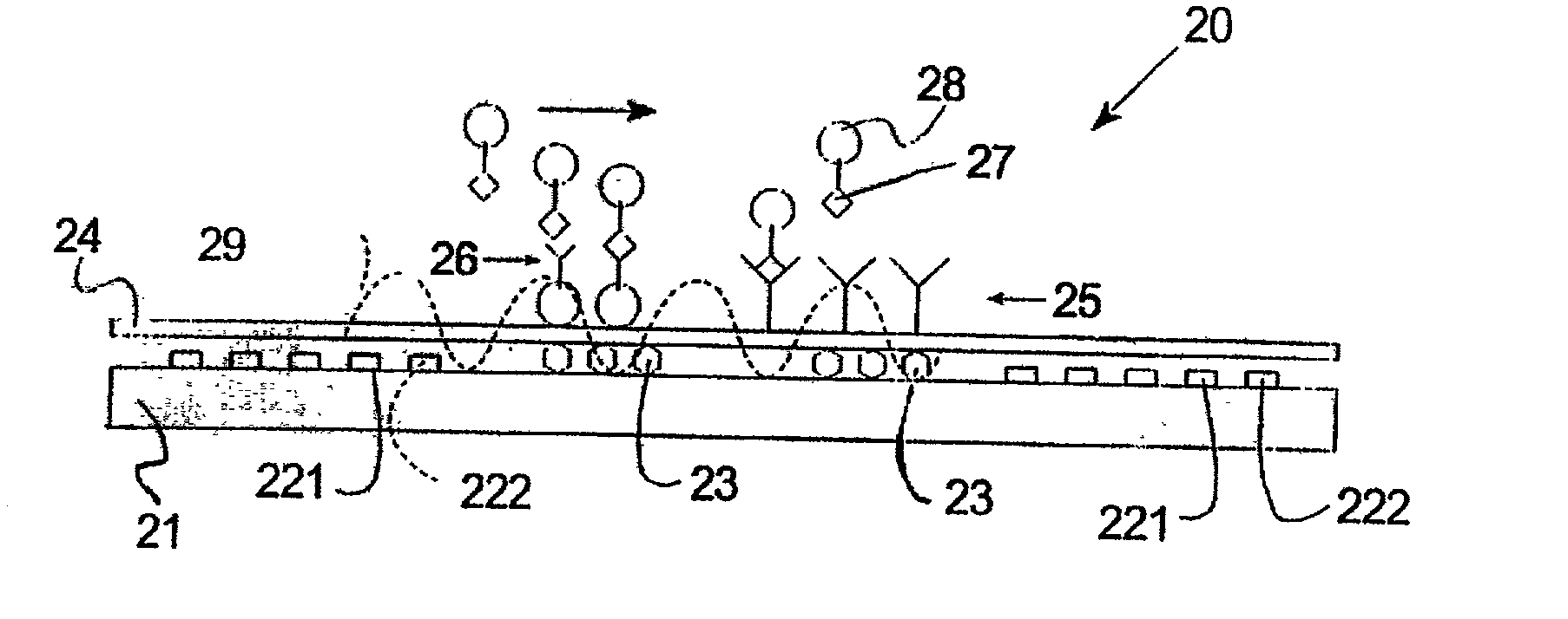
[0046] The general idea of the present invention is to manipulate small particles in order to bring one or more to a specific location on the surface of the substrate using individually addressable 
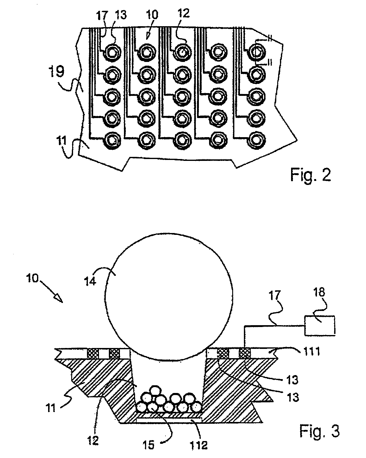
magnetic field(s), or other force transduction fields, as a driving force for particle manipulation. The surface of the substrate may be either patterned in a particular manner, or not. When the substrate includes craters (with or without a pattern) as shown in FIG. 3, some particles may be used as caps or lids to close craters as described earlier. When the substrate is left without a pattern or patterned in a different manner the particles can be used mainly as a way to enhance sensitivity of detection of the processes taking place in the device (e.g., on the surface of the substrate).
[0065] FIG. 13 illustrates a modular arrangement similar to the arrangement shown in FIG. 12, including an additional interface module 160 including micro-optics, such as an array of micro-lenses, to enhance detection by the sensor array 150.
[0066] To open a closed crater, or a filled pocket, a repelling field is generated either externally or by inverting the direction of the current flowing through the coils. It is also possible to terminate the current through the coil, whereby the particle may be released due to shear force from a flowing fluid or due to gravitational forces, e.g., if the craters are positioned "upside down". In pocket embodiments, controlled release and retention of beads may be facilitated by introducing an appropriate bead transducing field, e.g., coils to produce a magnetic field. Electrostatic and / or electrowetting field transducing means may also be implemented. Also, a physical armature may be provided proximal each bead retaining pocket.
[0067] The simple actuation of the crater lid using current-controlled magnetic field(s) and the potentially large number of craters on a chip makes it desirable that the chip is operated automatically through a controlling arrangement. The chip is preferably provided with an interface device that establishes electrical connection with the chip and provides control of the handling of the surrounding fluid with the beads and chemicals. After use the chip may be removed for cleaning and reuse or disposal. The interface device is preferably configured to connect to a computer equipped with suitable software to control the sequence of operations on the craters and the liquid handling system. The software also preferably provides an interface (e.g., GUI) for the user to establish process sequences and to plan the states of the crater lids at each stage in each sequence.

Problems solved by technology

A lid may or may not be completely liquid-tight, but mixing of the medium outside an enclosed well with the medium contained inside a well will be dramatically slowed.

Method used


Image

  • Systems and methods for localizing and analyzing samples on a bio-sensor chip
  • Systems and methods for localizing and analyzing samples on a bio-sensor chip
  • Systems and methods for localizing and analyzing samples on a bio-sensor chip

Examples


Embodiment Construction

are Given for Enhancing the Understanding of the Invention:

[0071] According to a first example, liquid A containing magnetic beads is introduced to the surface of a chip including an array of craters. User selected craters 12 are energized and hence capped. The remaining beads are flushed away with a cleaning liquid. Now liquid B is introduced, containing small (much smaller than the capping beads) particles, called X, made of a material interesting to the user. Only uncapped craters will accept X. Then, more magnetic capping beads are introduced and selected craters are capped, trapping X. Cleaning liquid is used to flush all excess away. A liquid containing chemical reagent Y is then introduced and some craters are selectively opened. X and Y are allowed to mix and react, but only in the user selected areas. This reaction can be followed using sensing techniques, for example using optical techniques. Other detection techniques easily incorporated into the present embodiment are me...


PUM


Abstract

Chips that include one or more particle manipulation mechanisms, or force transduction elements, provided at specific locations to manipulate and localize particles proximal the substrate surface. In one embodiment, individually addressable magnetic control mechanisms such as electric coils are provided at specific locations to create a magnetic field to attract magnetic particles, such a magnetic or magnetizable beads, to those specific locations. In another embodiment, electrostatic control mechanisms such as electrodes are provided to attract and manipulate electrically charged micro-particles. A location may include a crater or well formed in the substrate, or it may include an element on the surface of the substrate. In some embodiments, one or more sensors are located proximal specific locations, e.g. specific craters, so as to analyze specific conditions at each location. In other embodiments, multiple locations share one or more sensors.

Description

[0001] This application is a continuation-in-part of U.S. Ser. No. 9 / 963,866, filed Sep. 26, 2001, which is a continuation of U.S. Ser. No. 09 / 938,471, filed Aug. 23, 2001, which claims the benefit of U.S. Provisional Serial No. 60 / 288,015, filed Aug. 24, 2000, each of which is hereby incorporated by reference in its entirety.BACKGROUND OF INVENTION[0002] 1. Technical Field[0003] The present invention relates generally to methods, systems and arrangements for manipulating, localizing and analyzing samples, and more particularly to systems, methods and device arrangements for manipulating, localizing and analyzing samples, such as chemically or biologically active species on microbeads, on a bio-sensing device.[0004] 2. Background Information[0005] There exists an enormous number of processes occurring in an organism over a given unit of time and also in each cell of the organism. One needs therefore fast techniques that enable acquisition of information about such processes in paral...

Claims


Application Information

Patent Timeline
IPC IPC(8): B01J19/00B01L3/00C40B40/06C40B60/14G01N35/00G06F7/72
CPCB01J19/0046Y10T436/25B01J2219/0034B01J2219/00439B01J2219/00459B01J2219/005B01J2219/00585B01J2219/00596B01J2219/00605B01J2219/00612B01J2219/00648B01J2219/00659B01J2219/00722B01L3/502738B01L3/502761B01L2300/049B01L2400/0633C40B40/06C40B60/14G01N27/745G01N2035/00247G01N2035/00574G06F7/723G11C7/1066B01J2219/00317G01N35/0098
Inventor OTILLAR, ROBERTSTOREK, DAVID
Owner OTILLAR ROBERT P
Why Eureka
Try Eureka