
Processes for manufacturing organochlorosilanes and dipodal silanes and silanes made thereby

Active Publication Date: 2005-02-03
GELEST
View PDF3 Cites 24 Cited by
  • Summary
  • Abstract
  • Description
  • Claims
  • Application Information

AI Technical Summary

Benefits of technology

[0022] A particular advantage of the present invention is that it provides a continuous process for the dehydrohalogenative coupling reaction of hydrido functional chlorosilanes with alkyl halides and alkenes in the presence of a homogeneous phosphonium catalyst solution. The invention also allows the production of dipodal silanes by the double hydrosilylation of alkenes, preferably to produce vicinal disilyl derivatives.
[0023] Still further, the invention allows the production of silane products at relatively low or moderate pressures, for example less than 1000 p.s.i. In so doing, this invention controls the exposure of reactants to catalyst at elevated temperatures and minimizes or eliminates by-product formation.
[0024] The processes of the present invention provide greater flexibility in producing organochlorosilanes and dipodal silanes, using relatively short residence times, reducing the amount of waste generated, and allowing recycle of the catalyst. This in turn provides a process with improved process economics on a commercial scale. As a result, this invention provides the ability to produce organochlorosilanes and dipodal silanes on a continuous basis by processes which are more efficient than those of the prior art.
[0025] Particularly preferred is the use of the processes of this invention to produce 1,2-disilyl derivatives of alkenes which have utility as coupling agents and as surface modifiers of substrates for water repellency and in diagnostic applications.
[0026] Stated otherwise, the present invention relates to processes, including continuous processes, for preparing silyl and disilyl derivative compounds of organic halides and alkenes, including organochlorosilanes and dipodal silanes, wherein the processes comprise a dehydrohalogenative coupling of hydridochlorosilanes with either the organic halide or the alkene in the presence of a quaternary phosphonium salt catalyst. Where the processes of this invention involve reacting an alkene with a hydridochlorosilane, it is understood that the dehydrohalogenative coupling reaction is followed by a hydrosilylation reaction to produce, silylated derivative compounds, including vicinal disilyl derivative compounds, of the alkene.
[0027] Dehydrochlorinative coupling reactions for preparing organochlorosilanes are known in the art, for example from U.S. Pat. No. 6,392,077 of Jung et al and Kang, Seung-Hyun et al, “Phosphonium Chloride-Catalyzed Dehydrochlorinative Coupling Reactions of Alkyl Halides with Hydridosilanes,”Organometallics, 22:529-534 (2003), the disclosures of which are incorporated herein by reference. The processes of the present invention can use virtually any of the hydridochlorosilanes (also known as “hydrochlorosilanes”) and organic halides to produce virtually any of the organochlorosilanes disclosed by Jung et al and Kang et al in these references, as well as others which will be apparent to those skilled in the art based on the present disclosure.

Problems solved by technology

On a commercial scale, this is a labor- and time-consuming operation.
The use of sealed tube reactors also causes redistribution of initial by-products of the reaction resulting in such hazardous materials as dichlorosilane and silane.
This is a cumbersome process which requires reacting a chlorosilane with a stoichiometric amount of an amine, which generates a considerable amount of waste by-products.
Amine hydrochloride salts are difficult to filter and are often soluble in the product.
As a result, further filtration after product purification is required, and still the amine hydrochloride salts continue to drop out of solution after the products have been standing for extended periods of time.
Thus, the large scale production of organochlorosilanes and dipodal silanes by the above mentioned batch process is cumbersome, expensive and, in the case of the Benkesser process, generates excessive waste, such as amine hydrochloride salts and, in the Jung process, is subject to significant by-product generation, attributed to prolonged exposure to the catalyst at elevated temperatures and pressures resulting in the formation of by-products, such as dichlorosilane and silane gas which are difficult to handle and pyrophoric.

Method used


Image

  • Processes for manufacturing organochlorosilanes and dipodal silanes and silanes made thereby
  • Processes for manufacturing organochlorosilanes and dipodal silanes and silanes made thereby
  • Processes for manufacturing organochlorosilanes and dipodal silanes and silanes made thereby

Examples


example 1

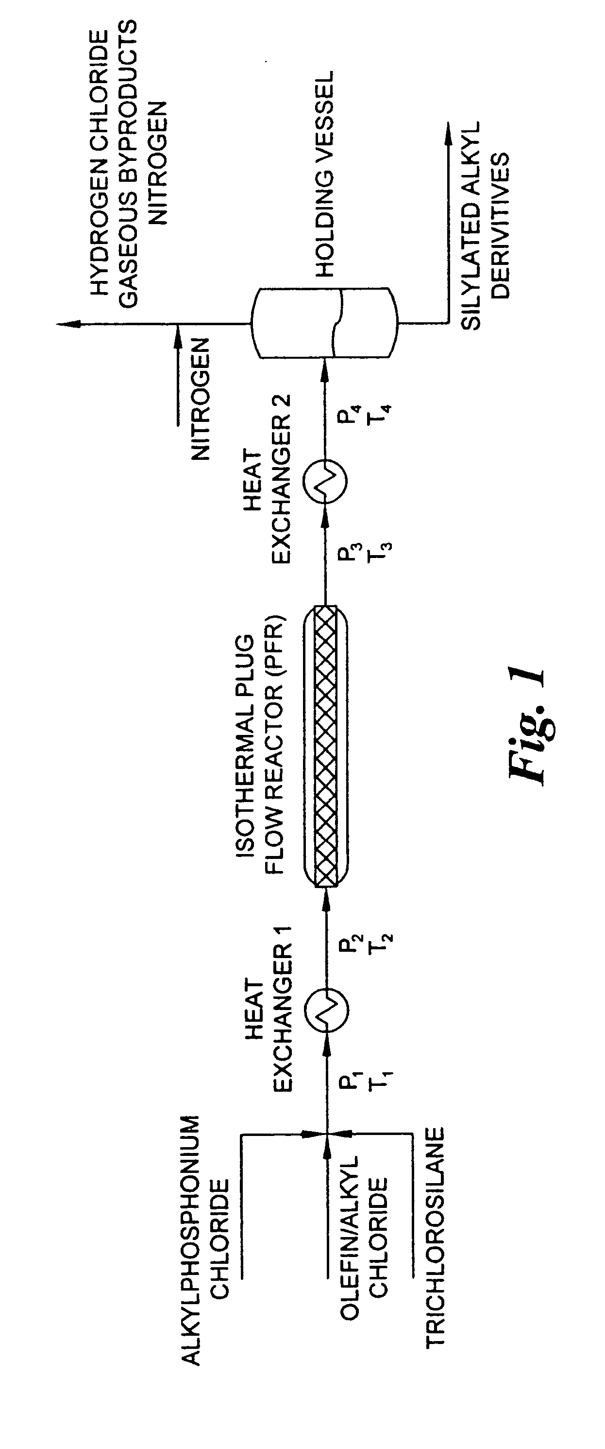
[0062] This example describes a reactor design which is a continuous PFR having three heating zones, such as described above in connection with FIG. 1. More specifically, the heating zones are: Zone 1 which pre-heats the reactants to 180° C.; Zone 2 which has a volume of 2851.7 milliliter equipped with 24 static mixing elements and maintains the reaction mixture at 180° C. for the desired residence time; and Zone 3 which reduces the reaction mixture temperature from the reaction temperature to room temperature. Trichlorosilane, benzyl chloride and a 50% solution of tetradecyltributylphosphonium chloride in toluene are fed to the PFR reactor by a dual feed pump in a 3:1:0.1 molar ratio, respectively, at a rate molar to maintain a one hour residence time in the reactor. The reaction pressure is adjusted by utilizing a back-pressure regulating valve set to 350 p.s.i. The reaction products are collected in a vessel which allows a by-product of hydrogen chloride to be vented to an acid g...

example 2

[0063] By utilizing the same reactor, ancillary equipment and procedure as in Example 1 above, trichlorosilane, 1-decene and tetradecyltributylphosphonium chloride 50% in toluene are fed in a 2:1:0.1 molar ratio, respectively, at a rate to maintain a two hour residence time. As in Example 1, the reaction mixture is maintained at a temperature of 180° C. and a pressure of 350 p.s.i. The reaction mixture is collected in a vessel which allows a by-product of hydrogen chloride to be vented to an acid gas scrubber. A gas chromatogram of the reaction mixture shows that the mixture is 5.4 weight percent decyltrichlorosilane, 70.3 weight percent 1,2-bis(trichlorosilyl)decane (a novel compound), trichlorosilyldichlorosilyldecane isomers, and a balance of tetrachlorosilane and toluene.

example 3

[0064] By utilizing the same reactor, ancillary equipment and procedure as Example 1 above, trichlorosilane allyl chloride and tetrabutylphosphonium chloride 50% in toluene are fed in a 2:1:0.05 molar ratio, respectively, at a rate to maintain a one hour resistance time. Zone 2 of the reactor maintains the temperature of the reaction mixture at 130° C., and the pressure in the reactor is adjusted by setting the back-pressure regulated valve to 150 p.s.i. to 200 p.s.i. The reaction mixture is collected in a vessel which allows the hydrogen chloride by-product to be vented to an acid gas scrubber. A gas chromatogram of the reaction mixture shows that the mixture was 48 wt % allyltrichlorosilane, 3 wt % chloropropyltrichlorosilane and 2 wt % 1,3-bis(trichlorosilyl)propane, the balance being composed of tetrachlorosilane and toluene.


PUM


Abstract

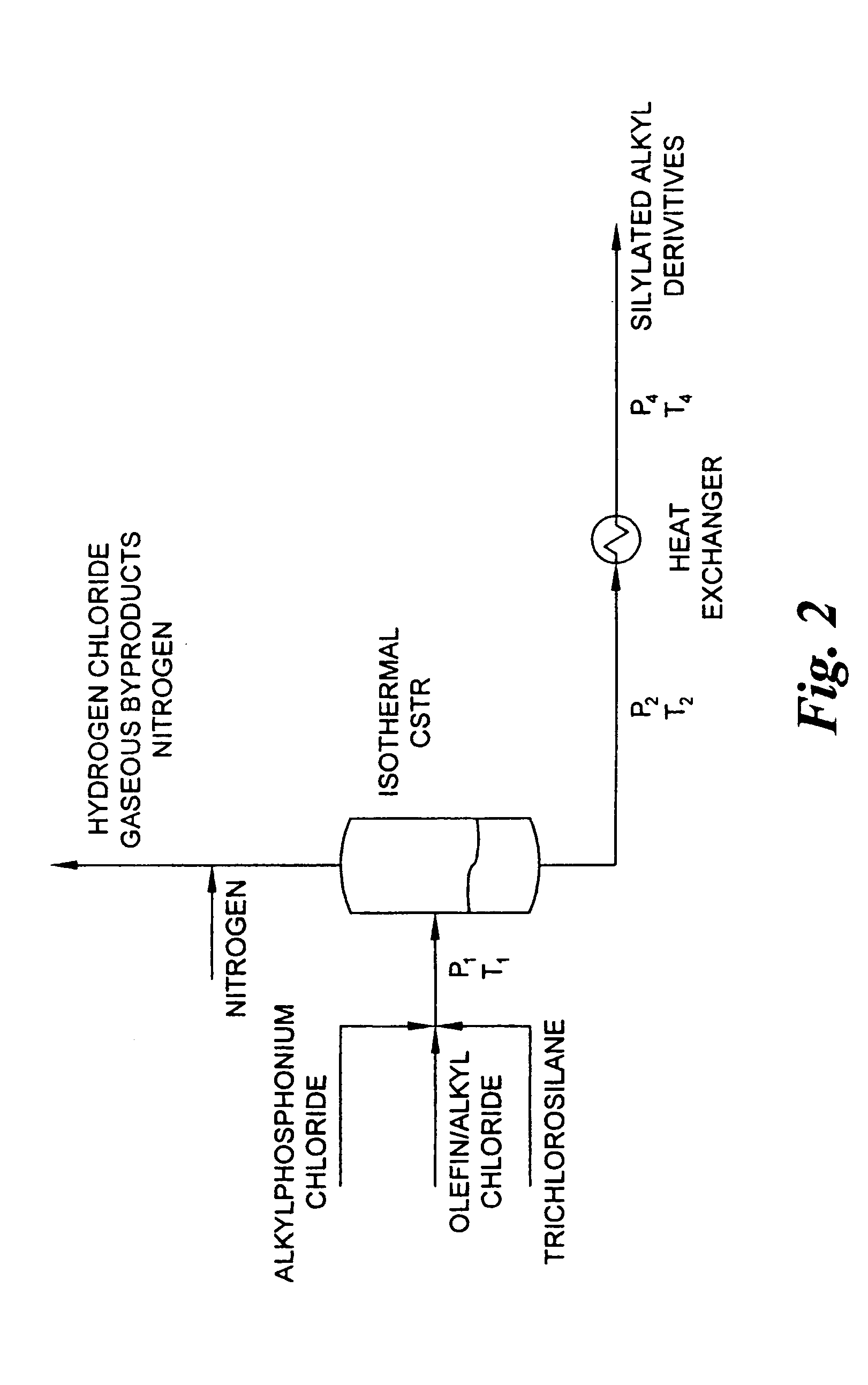
Processes are provided for producing organchlorosilanes and dipodal silanes in which an organic halide or alkene or chloralkene is reacted with a hydridochlorosilane in the presence of a quarternary phosphonium salt catalyst by providing sufficient heat to effect a dehydrohalogenative coupling reaction and / or a hydrosilylation reaction and venting the reaction to control reaction pressure and to remove gaseous byproducts from the reaction. The processes are preferably continuous using a catalyst in fluid form at reaction pressures not exceeding about 600 psi. The reactions may be carried out substantially isothermally and / or isobarically, for example in a plug flow reactor or continuous stirred tank reactor. The processes may produce novel silylated compounds including 1,2-bis(trichlorosilyl)decane or 1,2-bis(trimethoxysilyl)decane.

Description

CROSS-REFERENCE TO RELATED APPLICATION [0001] This application claims the benefit of provisional patent application 60 / 474,440, filed May 30, 2003, the disclosure of which is incorporated herein by reference.BACKGROUND OF THE INVENTION [0002] This invention relates to processes, including continuous processes, for the production of silylated derivative compounds of organic halides and alkenes, including organochlorosilanes and dipodal silanes, useful in a variety of applications including as coupling agents and as surface modifiers of substrates related particularly to water repellency and diagnostic applications. [0003] It has been reported in U.S. Pat. No. 6,392,077 of Jung, et al. that organochlorosilanes can be prepared in a batch process by a dehydrohalogenative coupling reaction of an alkyl halide with a hydrido functional chlorosilane in the presence of a solid phosphonium catalyst or solid supported catalyst, as further described in U.S. Pat. No. 4,613,491 of Jung, et al. [0...

Claims


Application Information

Patent Timeline
IPC IPC(8): C07F7/12C07F7/18
CPCC07F7/1836C07F7/12C07F7/1804
Inventor JANEIRO, BENIGNO A.ARKLES, BARRY C.
Owner GELEST
Learn More