
Solid-state diode pumped laser employing oscillator-amplifier

Inactive Publication Date: 2004-02-12
LAMBDA PHYSIK
View PDF6 Cites 16 Cited by
  • Summary
  • Abstract
  • Description
  • Claims
  • Application Information

AI Technical Summary

Benefits of technology

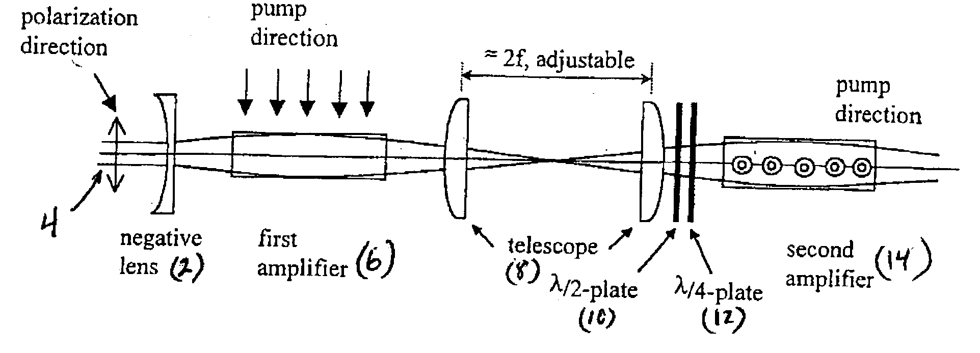
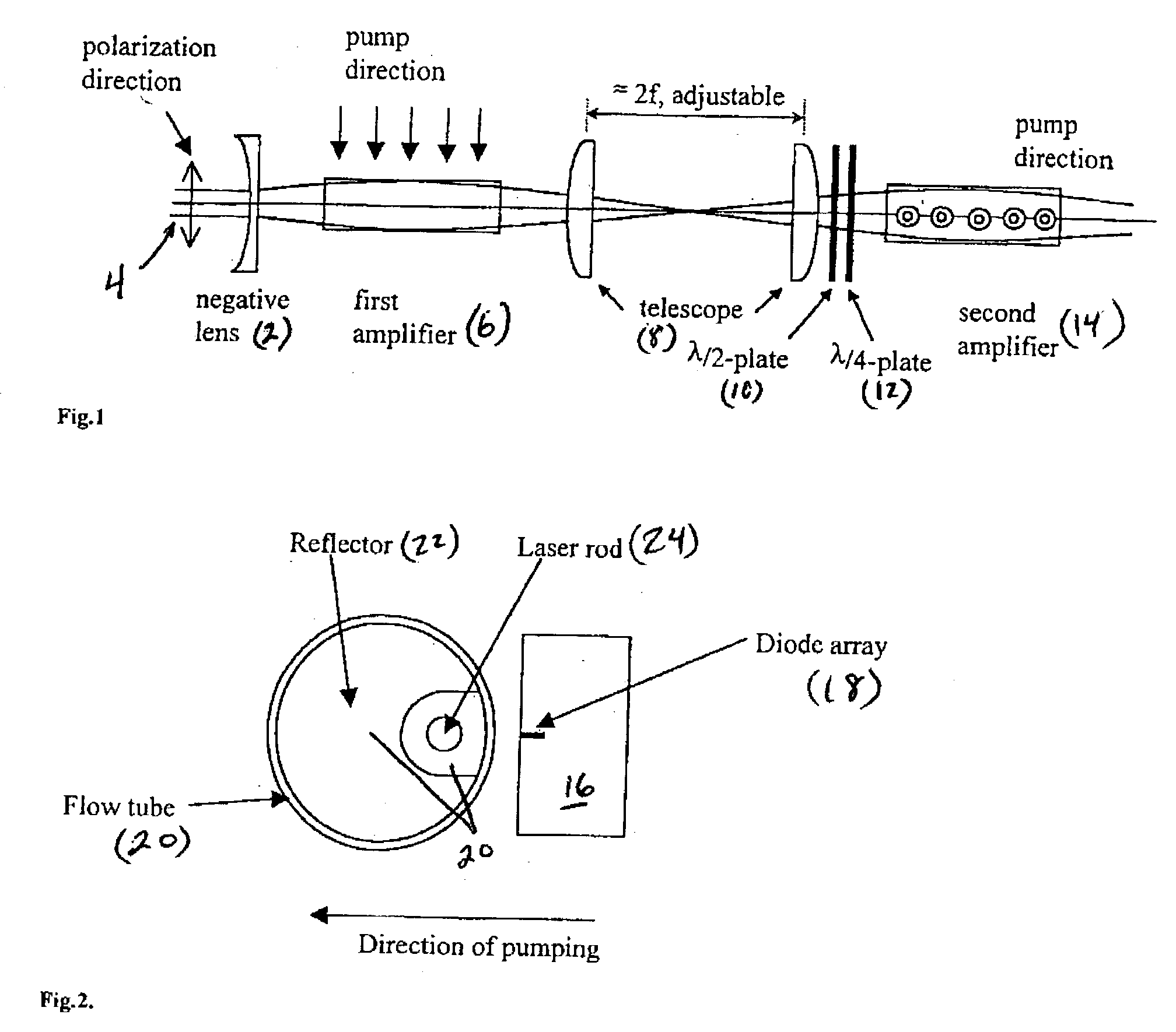
[0045] To obtain high output power with high beam quality from a solid state laser (such as Nd:YAG laser), an oscillator-amplifier setup is preferably employed in accordance with a preferred embodiment. The master oscillator emits a TEM.sub.00 beam 4 with superior beam quality and high degree of polarization, but with comparably low output power. This output is then amplified in one or more amplifier stages, e.g., stages 6 and 14 of FIG. 1. To maintain high beam quality, the beam is preferably not distorted in the amplifier stages 6, 14. The amplifiers 6, 14 are more sensitive to distortions in the laser gain variations across the rod, because the beam passes only a single time through the laser rod, compared with multiple passes in the oscillator. Therefore, in the oscillator, the beam undergoes multiple steps of spatial filtering before it is output and thus acquires high spatial quality.
[0047] FIG. 2 schematically illustrates a cross-sectional view of the preferred oscillator, and of a pump chamber of a stage of the amplifier. The operation of this device is described in greater detail at the Ser. No. 09 / 938,329 application, incorporated by reference above. The preferred embodiment preferably uses pump chambers ("heads") 16 incorporating a single diode array 18 (consisting typically of 3 bars) closely spaced to the flow cell 20, which in turn comprises a diffuse reflector 22 and the laser rod 24. The preferred design has several advantages such as compactness, simplicity, and efficiency.
[0049] The preferred embodiments provide improved quality of the output beam by reducing the negative effects described in the background above. In applications such as micro-machining, this permits the creation of higher quality and smaller size micro-features, and also the processing of tougher materials at higher throughput, because the higher-quality beam can be focused into a spot of smaller size and higher intensity.
[0060] In addition to the fill factor, we found experimentally that the divergency of the beam in the rod is also important. There is an effect of the divergency on the quality of the output beam. The optimal divergency of the incident beam is such that the output beam converges, as shown in FIG. 1. It is possible because the rod acts as a positive lens. Therefore, the wavefront curvature radius of the input beam is preferably adjusted to about twice the focal length of this lens to make the output beam converge, with approximately a same degree as is the input divergence. The exact value of the focusing power of the amplifier stages and the divergence of the beam originating from the oscillator are not known precisely in general, because these parameters vary from laser to laser. To fill both amplifier stages perfectly, it is preferred to adjust 1) divergency and diameter of the beam at the entrance of the first amplifier stage, and 2) same beam parameters in between the amplifier stages. The negative lens 2 (see FIG. 1) in front of the first stage allows an increase of the divergency of the beam. In order to adjust the beam diameter, one can adjust the distance between the lens 2 and the first stage 6. An additional benefit of this optimal mode size matching is that these rods also act as apertures, thus defining the circularity of the beam.
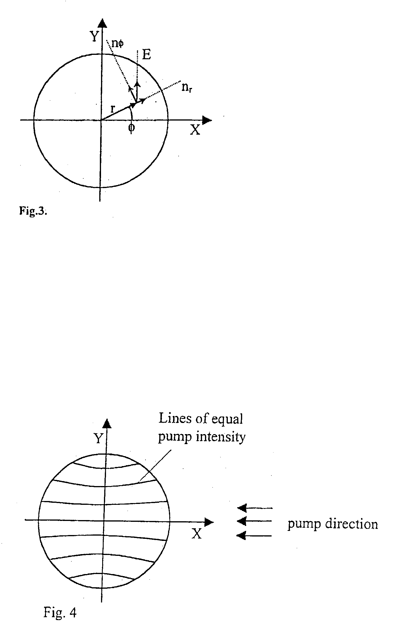
[0062] As is discussed above, the pump light can induce stress in the laser rod, which, can in turn, lead to induced birefringence. This means that the linearly polarized light may undergo some depolarization, whose magnitude depends on the position in the rod. The locations on the axes X and Y (see FIG. 3) do not introduce any depolarization, while the areas around 45.degree., 135.degree., 225.degree., 315.degree. produce an elliptically polarized beam at the output, instead of a linearly polarized one. The total depolarization of the entire amplifier can be reduced by placing an additional .lambda. / 4-plate 12 in between the stages 6,14, with its optical axis oriented at 0.degree. to either the X or Y axis. Linearly polarized light will not be affected by this plate, but depolarized light from the areas at 45 degrees will receive a quarter-wave phase shift between the fast and slow components. This effectively makes the fast component from the first stage 6 to become a slow component in the second stage 14, and vice versa. Therefore, a phase shift that occurred in the first stage 6 is compensated for in the second stage 14. Alternatively, a quartz rotator (not shown) can be used in place of both the .lambda. / 4 plate 12 and .lambda. / 2 plate 10. An advantage here is that there are fewer optical components. However, use of a quartz rotator may increase the cost of the system.

Problems solved by technology

The laser gain profile may vary across the rod in a way that the gain distribution is not uniform and not radially-symmetric.

Method used


Image

  • Solid-state diode pumped laser employing oscillator-amplifier
  • Solid-state diode pumped laser employing oscillator-amplifier
  • Solid-state diode pumped laser employing oscillator-amplifier

Examples


Embodiment Construction

[0064] Many alternative embodiments are possible. For example, the telescope 8 may include a pair of negative lenses, rather than the preferred positive lenses. Other kinds of pump heads may be used. Multiples of the two stages of the amplifier may be used, e.g., 4, 6, 8, . . . The additional laser rods will preferably have telescopes and waveplates or quartz rotators in between the stages.

[0065] While exemplary drawings and specific embodiments of the present invention have been described and illustrated, it is to be understood that the scope of the present invention is not to be limited to the particular embodiments discussed. Thus, the embodiments shall be regarded as illustrative rather than restrictive, and it should be understood that variations may be made in those embodiments by workers skilled in the arts without departing from the scope of the present invention as set forth in the claims that follow, and equivalents thereof.


PUM


Abstract

A solid-state laser system includes a solid state oscillator for generating a laser beam and a multiple stage amplifier for increasing an energy of the beam. The oscillator includes an elongated housing having an elongated cavity defined therein, a solid state rod disposed within the cavity, a pumping source for exciting laser active species within the rod, and a resonator including the rod disposed therein for generating a laser beam. The multiple-stage amplifier preferably includes an even number of stages. One or more pairs of compensating stages may be mutually rotated about the beam axis by substantially 90°, with each pumping direction parallel to the polarization direction of the beam. A first stage may be side-pumped by a pumping radiation source in a direction substantially parallel to a polarization direction of the beam generated by the oscillator resonator. A divergence adjusting optic may be disposed before at least one stage of the amplifier for adjusting a divergence of the beam prior to entering the amplifier stage. A divergence adjusting optic may be disposed after the amplifier stage having the divergence adjusting optic before it and before a second amplifier stage, and may be adjustable as to its divergence adjustment.

Description

PRIORITY[0001] This application claims the benefit of priority to U.S. provisional patent application serial number No. 60 / 355,078, filed Feb. 7, 2002.[0002] 1. Field of the Invention[0003] The invention relates to solid state lasers, and particularly to a high power two-stage solid-state oscillator-amplifier system[0004] 2. Description of the Related Art[0005] Many emerging applications of solid-state lasers require high quality and high power laser beams. Examples of such applications are micromachining of micro-vias in microelectronics, fuel injector nozzles in automotive industry, extrusion dies, miniature medical devices, and various components for fiber-optics communication devices, among others known to those skilled in the art. For these applications and potentially many others, it is desired that the parameters of the beam, especially the spatial intensity distribution, be substantially constant throughout the useable lifetime of the laser (typically up to 20,000 hours). It...

Claims


Application Information

Patent Timeline
IPC IPC(8): H01S3/06H01S3/091H01S3/092H01S3/094H01S3/0941H01S3/23
CPCH01S3/005H01S3/0407H01S3/061H01S3/2316H01S3/094084H01S3/0941H01S3/08072
Inventor GOVORKOV, SERGEI V.WIESSNER, ALEXANDER OLIVER WOLFGANG
Owner LAMBDA PHYSIK
Learn More