
Electrochemical pressurizer/purifier of hydrogen for operation at moderately elevated temperatures (including high-temperature electrochemical pump in a membrane generator of hydrogen

Active Publication Date: 2003-08-21
HYDRIP LLC
View PDF3 Cites 26 Cited by
  • Summary
  • Abstract
  • Description
  • Claims
  • Application Information

AI Technical Summary

Benefits of technology

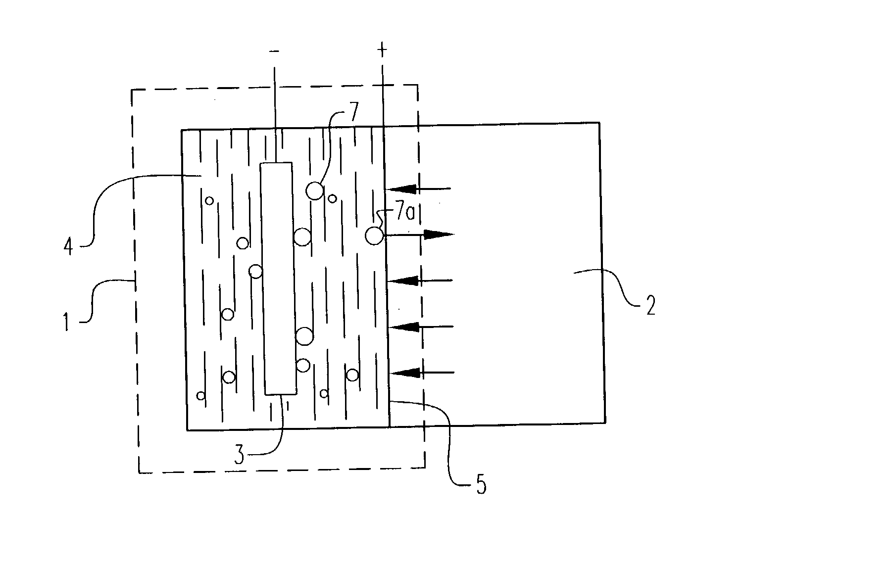
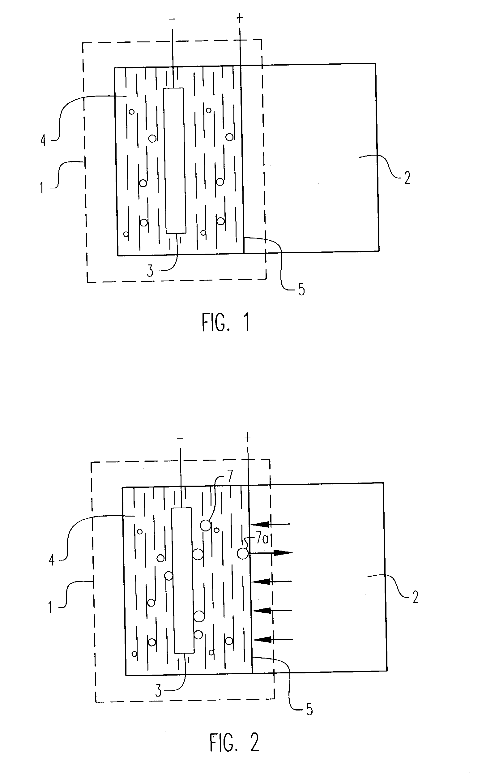
[0012] It is a further object of this invention to provide in such a new generator, a cathodic high pressure chamber producing therein pure hydrogen pressures in excess of 1000 psig and with a cathode with means for reducing the hydrogen overvoltage thereon.

Problems solved by technology

However, these benefits are attained at the expense of having to separate the sweep gas from the hydrogen product and having to pressurize the pure hydrogen product.
Using more sweep gas per unit of hydrogen permeated evidently provides greater benefits but at a greater expense for the subsequent separation / pressurization.
(This fuel cell was abandoned due to the costly removal of carbon dioxide from large quantities of cathodic air.)
Moreover, the cathodic evolution of hydrogen is now subject to an overvoltage the magnitude of which depends not only on current density and temperature, but significantly on the nature of the cathode.
This electrolyte / membrane is practically limited to excessively high temperatures due to the very low protonic conductivity of the membrane.

Method used


Image

  • Electrochemical pressurizer/purifier of hydrogen for operation at moderately elevated temperatures (including high-temperature electrochemical pump in a membrane generator of hydrogen
  • Electrochemical pressurizer/purifier of hydrogen for operation at moderately elevated temperatures (including high-temperature electrochemical pump in a membrane generator of hydrogen
  • Electrochemical pressurizer/purifier of hydrogen for operation at moderately elevated temperatures (including high-temperature electrochemical pump in a membrane generator of hydrogen

Examples


example 1

[0050] An electrochemical cell was constructed using two standard 1 / 2 inch stainless steel blind pipe flanges. Stainless steel tubing was fitted to holes drilled through the flanges to provide gas inlet and outlet ports to each flange. The tubes were welded to the flange to provide leak-tight seals.

[0051] Leak-tight current collector / electrode assemblies were fabricated by diffusion bonding (see U.S. Pat. No. 5,904,754) a 0.001 inch thick.times.1.375 inch diameter Pd60 / Cu40 weight percent foil disc to one side of a copper washer (1.375 inch outside diameter.times.1.125 inch inside diameter.times.0.010 inch thick). The opposing side of the copper washer was diffusion bonded to a copper foil current collector containing two holes positioned to match the gas inlet and outlet ports in the flanges. A 100.times.100 mesh stainless steel wire cloth disc was included on the inside of the copper washer to provide a flowfield for gases and support the membrane electrode. The copper current col...

example 2

[0060] An electrochemical cell of the type described in Example 1 was used with the following modifications:

[0061] (a) The electrolyte / matrix was 1 inch in diameter

[0062] (b) The second gasket had a 1 inch diameter center hole

[0063] (c) The cathode / current collector was replaced with a 1 inch diameter porous nickel foam (Eltech Systems) against the electrolyte / matrix and nickel foil current collector. A 1 inch diameter 100.times.100 mesh nickel woven wire cloth disc was placed between the foam and foil.

[0064] The startup procedure described in Example 1 was followed except that the electrochemical cell was positioned with the electrodes horizontal and cathode on top. Measured cathodic hydrogen flows were within experimental error of the expected flows according to Faraday's Law. Hydrogen compression was verified by closing the cathode gas outlet valve an observing a constant current (0.12 A / cm.sup.2) cathodic pressure increase to 10 psig from an atmospheric pressure anode hydrogen f...

example 3

[0065] An electrochemical cell of the type described in Example 1 was fed a mixture of nominally 40% hydrogen / 60% nitrogen at atmospheric pressure resulting in a sub-atmospheric partial pressure of hydrogen of about 6 psia. Approximately 120 cc / min of this gas mixture was fed to the anode compartment of the electrochemical cell operating at ca. 2 amps. Outlet flows were 106 cc / min. and 14 cc / min. from the anode and cathode compartments, respectively, resulting in about 30% of the hydrogen feed recovered as pure hydrogen and compressed to atmospheric pressure.

[0066] The inlet flow of this atmospheric pressure gas mixture was reduced to about 34 cc / min. While still operating at ca. 2 amps, the outlet flows were about 20 cc / min. and 14 cc / min. from the anode and cathode, respectively, resulting in nearly 100% of the hydrogen feed recovered as pure hydrogen and compressed to atmospheric pressure. Further hydrogen compression was verified by closing the cathode gas outlet valve and obser...


PUM

PropertyMeasurementUnit
Temperatureaaaaaaaaaa
Thicknessaaaaaaaaaa
Angleaaaaaaaaaa

Abstract

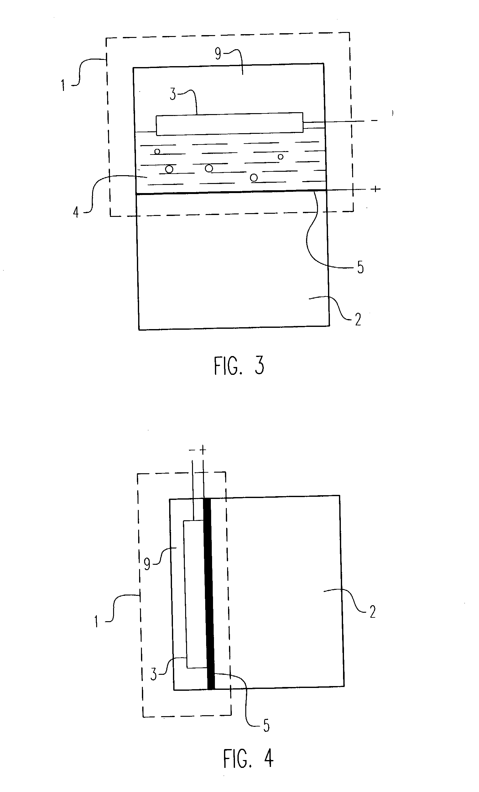
An electrochemical generator of pure pressurized high pressure hydrogen comprising a molten hydroxide or eutectic mixture electrolyte electrochemical pressurizing chamber bounded by a hydrogen-selective anode and a hydrogen-selective otherwise gas impermeable cathode respectively connected to a D.C. power supply, with the pressurizing chamber maintained at a temperature between the melting point of the electrolyte and about 600° C., wherein, upon passing D.C. current between the anode and cathode, pure hydrogen arriving on the electrolyte bounding with the anode substantially instantaneously reacts with hydroxyl ions from the electrolyte to form water and electrons and evolves pressurized pure hydrogen gas on the cathode, with such substantially instantaneous reaction at the anode creating a suction effect which effectively pumps pure hydrogen permeating through said anode.

Description

[0001] The present invention relates to generating hydrogen for a wide variety of chemical applications and as a fuel, by way of example, for proton exchange membrane (PEM) fuel cells; and more particularly, generating pure hydrogen at a moderately elevated temperature in an electrochemical pressurizer connected to a metallic hydrogen-selective membrane bounding a chamber containing hydrogen at a low pressure.[0002] Part of this invention is the subject matter of Provisional Patent Application Serial No. 60 / 358620 entitled High-Temperature Electrochemical Pump in a Membrane Generator of Hydrogen, filed Feb. 1, 2002, which describes generating electrochemically hydrogen, at a moderately elevated temperature (therein called "High-Temperature") in an anodic chemical reactor chamber and simultaneously permeating pure hydrogen in situ from the reactor chamber through an electron conducting, hydrogen selective membrane bounding thereto, e.g., a palladium-bearing tube or foil, into an inte...

Claims


Application Information

Patent Timeline
IPC IPC(8): B01D53/22B01D53/32C01B3/50H01M8/06H01M8/10
CPCB01D53/228B01D53/32B01D2257/108C01B3/501C01B2203/041C01B2203/0495Y02T90/32H01M8/0681H01M8/0687H01M2008/1095H01M2250/20Y02E60/50H01M8/0612Y02T90/40B01D53/00C01B3/50C25B1/02
Inventor JUDA, WALTERBOMBARD, R. TODDKNEGER, CHARLES W.
Owner HYDRIP LLC
Learn More