
Methods and apparatus for rendering an optically encoded medium unreadable

an optical encoded medium and unreadable technology, applied in the field of optical encoded media unreadable methods and apparatuses, can solve the problems of unfavorable protection mechanisms, unfavorable protection mechanisms that rely on computer software to implement, and unfavorable protection mechanisms that can be defeated by additional computer softwar

Inactive Publication Date: 2002-06-20
FLEXPLAY TECH INC
View PDF0 Cites 58 Cited by
  • Summary
  • Abstract
  • Description
  • Claims
  • Application Information

AI Technical Summary

Benefits of technology

[0008] It is a second object and advantage of this invention to provide an improved system and method to render an optically readable media permanently unreadable, after having been read at least once.
[0021] In accordance with further embodiments of this invention an optically readable media has a patterned structure for encoding information that can be readout by application of light, and further includes a layer that is comprised of a volatile component and at least one other component. Removing at least some of volatile component by evaporation or sublimation causes an increase in at least one of photoabsorption or scattering with the remaining component, thereby rendering at least a portion of the encoded information unreadable. The other component can include a lactone dye, such as crystal violet lactone, and the volatile component can be, for example, NMP (N-methyl pyrrolidinone). In a further embodiment an organic material, such as CsF or KBr, is coated on the surface of the disk and provides a surface haze when exposed to water vapor or carbon dioxide, thereby increasing the scattering and decreasing the signal-to-nose ratio, and degrading the readout fidelity.

Problems solved by technology

However, this has proven to be a vexing problem that is not readily solved.
Unfortunately, such information may be distributed on write-protected disks, thereby rendering such erasure impossible.
Also, any protection mechanism that relies on computer software to implement has the potential to be defeated by additional computer software.
The darkening of the photochromic compound prevents a sufficient amount of readout light from being detected by the readout apparatus, thereby effectively rendering the optical disk unreadable.
At least one perceived disadvantage of this approach is that photochromic darkening is often reversible, which could be used to defeat the technique.

Method used


Image

  • Methods and apparatus for rendering an optically encoded medium unreadable
  • Methods and apparatus for rendering an optically encoded medium unreadable
  • Methods and apparatus for rendering an optically encoded medium unreadable

Examples


first embodiment

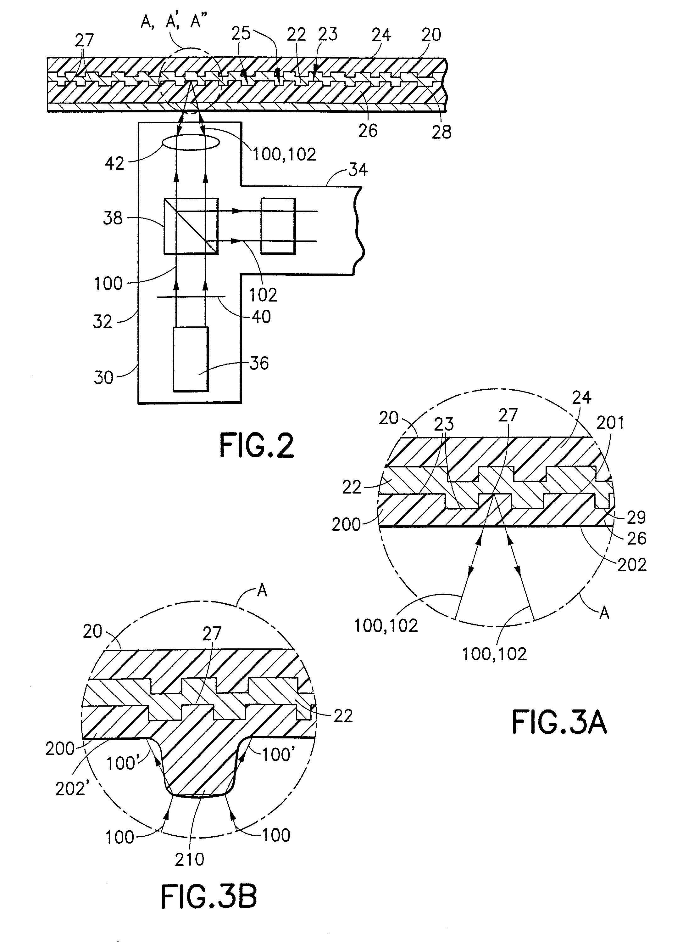
[0043] Referring now to FIGS. 3A and 3B, there is shown an enlarged cross-sectional view of a portion A of the optical disk 20 in accordance with this invention. The optical disk 20 is constructed so as to include a surface relief photopolymer layer 200. The surface relief photopolymer layer 200 is comprised of one or more polymers, such as, by example, an azobenzene containing polymer. It is known that an azobenzene containing polymer is capable of exhibiting a surface deformations in response to a presence of an optical intensity gradient.

[0044] Reference in this regard may be had to an article entitled "Gradient force: The mechanism for surface relief grating formation in azobenzene functionalized polymers", Applied Physics Letters, Vol. 72, No. 17, pps. 2096-2098, Apr. 27, 1998, J. Kumar et al. The authors report on the derivation of a model for the formation of holographic surface relief gratings in azobenzene functionalized polymers. Forces leading to migration of polymer chai...

third embodiment

[0059] Referring now to FIGS. 5A and 5B, there is shown an enlarged cross-sectional view of Section A" of the optical disk 20" in accordance with this invention. The optical disk 20" in this embodiment of the invention is substantially similar to the optical disk 20 described previously with reference to FIG. 2, except as otherwise noted below. As seen in FIGS. 5A and 5B, the optical disk 20" in accordance with this embodiment includes a substrate 400 which may be formed from a polycarbonate material disposed generally against the reflective surface 28" of the reflective layer 22" in the optical disk. Included between the substrate 400 and the reflective surface 28" of the disk 20" are regions or pockets 402A, 402B of an uncured photopolymer 402. As shown in FIG. 5A, the photopolymer 402 is disposed within the pits 27" formed in the reflective layer 22" of the optical disk 20". In an uncured state, the index of refraction of the photopolymer 402 is such that the interrogating beam 1...

example # 1

EXAMPLE #1

[0073] A solution of poly-p-(hydroxystyrene) (5 .mu.m), ethanol (10 mL), crystal violet lactone (200 mg) and NMP (3.0 mL) was prepared. A few drops were applied to a glass slide and the mixture was allowed to air dry at room temperature. The film which formed was soft and tacky to the touch but it was colorless. Color formation was followed over the course of several days through the use of a spectrophotometer.

3 Time (hours) Optical Density (607 nm) 0 0 18 0.181 85 0.242

[0074] Since the film formed in example #1 was soft and tacky formaldehyde was added to cross link the phenolic polymer.


PUM

PropertyMeasurementUnit
linear velocityaaaaaaaaaa
wavelengthsaaaaaaaaaa
spot sizeaaaaaaaaaa

Abstract

Methods and apparatus are provided for making an optically readable media unreadable. The method includes steps of (a) providing the media with an optically activated mechanism that degrades the reflectivity of a surface wherein information is encoded; (b) exposing the media to optical radiation for reading out the information; and, during the step of exposing, (c) initiating the operation of the optically activated mechanism. In this embodiment the step of initiating includes steps of (d) generating singlet oxygen in a layer disposed on the media; and (e) reacting the singlet oxygen with a metal-containing layer for oxidizing the surface of the metal-containing layer, thereby degrading the reflectivity of the surface. In a further aspect the optically activated mechanism causes a defocusing of a readout beam, thereby degrading reflection of the readout beam from a surface wherein information is encoded. In another embodiment the method deforms a surface of the layer resulting in readout beam aberration or in an inability to correctly stay on track. In another embodiment a portion of the surface is removed to the atmosphere, such as by evaporation of sublimation. In this embodiment a layer of the media is comprised of a volatile component and at least one other component. Removing at least some of volatile component by evaporation or sublimation causes an increase in at least one of photoabsorption or scattering or surface roughness with the remaining component, thereby rendering at least a portion of encoded information of the media unreadable, or affecting the tracking operation.

Description

[0001] Priority is herewith claimed under 35 U.S.C. .sctn.119(e) from copending Provisional Patent Application No. 60 / 090,682, filed Jun. 25, 1998. The disclosure of this Provisional Patent Application is incorporated by reference herein in its entirety.[0002] This invention relates to optically readable data storage media and, more particularly, to techniques to render said media unreadable after being read at least once.[0003] It is often desirable when distributing software or other information that is recorded on a medium to insure that only one party is enabled to read the recorded information. For example, a company that sells computer software will find it advantageous to enable only the purchaser to read the software from a disk and transfer or install the software to computer memory, such as a hard disk, while preventing subsequent access by other parties to the software. However, this has proven to be a vexing problem that is not readily solved.[0004] When the information ...

Claims


Application Information

Patent Timeline
Patent Type & Authority Applications(United States)
IPC IPC(8): B32BB32B3/00G11B7/241G03C1/73G11B3/70G11B7/0055G11B7/24G11B7/252G11B7/257G11B20/00G11B23/28
CPCG11B7/252G11B7/2534G11B7/2542G11B7/2575Y10S430/146G11B20/00086G11B20/00797G11B23/282G11B23/505G11B7/2585G11B7/26G11B7/241G11B2220/2587G11B2220/2545G11B2220/2562
Inventor LAWANDY, NABIL M.ZEPP, CHARLES M.NORLAND, KENNETH S.
Owner FLEXPLAY TECH INC
Learn More