
Exposure apparatus and exposure method

a technology of exposure apparatus and exposure method, which is applied in the field of exposure apparatus, can solve the problems of poor light absorption loss, inability to use reticle transfer systems, and bulky exposure apparatus, and achieve the effect of short master exchange time and low light absorption loss

Inactive Publication Date: 2002-06-13
CANON KK
View PDF0 Cites 11 Cited by
  • Summary
  • Abstract
  • Description
  • Claims
  • Application Information

AI Technical Summary

Benefits of technology

[0015] The present invention has been made to overcome the conventional drawbacks, and has as its object to provide a high-throughput exposure apparatus for realizing both low light absorption loss in the optical path of an exposure beam around a master and a short master exchange time.

Problems solved by technology

However, the prior arts suffer the following problems.
These systems are not practical reticle transfer systems in an exposure apparatus using an F.sub.2 excimer laser as described above.
If the atmosphere in the whole reticle transfer system disclosed is simply controlled to reduce a light absorber, the exposure apparatus becomes bulky, complicated in structure, and very high in cost.

Method used


Image

  • Exposure apparatus and exposure method
  • Exposure apparatus and exposure method
  • Exposure apparatus and exposure method

Examples


first embodiment

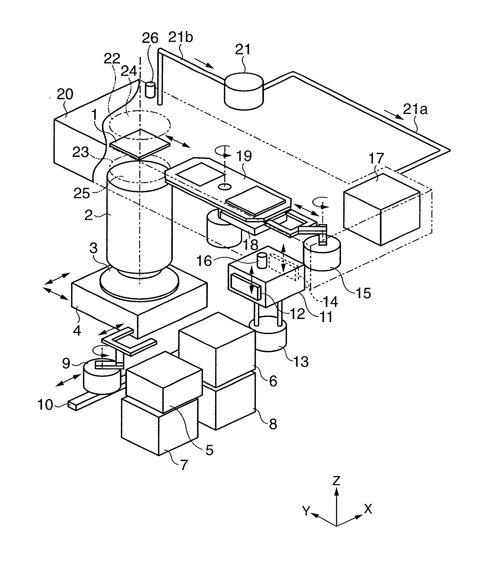
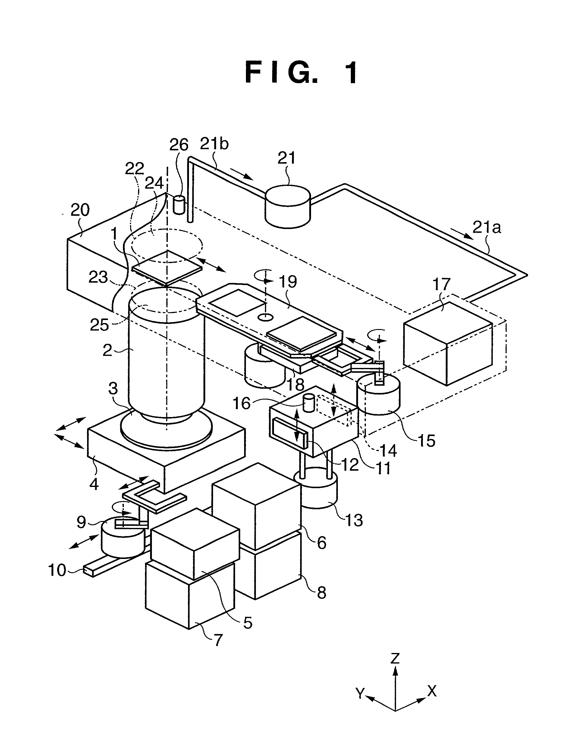
[0032] FIG. 1 is a perspective view showing an exposure apparatus according to the present invention. FIG. 1 particularly shows the interior of a chamber which covers the overall exposure apparatus, keeps the interior of the exposure apparatus at a predetermined temperature, and keeps dust to low level.

[0033] In FIG. 1, reference numeral 1 denotes a reticle bearing a circuit pattern. This circuit pattern is illuminated via an illumination optical system (not shown) with a beam emitted by an F.sub.2 excimer laser having an oscillation wavelength around 157 [nm]. The pattern is projected on a wafer 3 at a predetermined magnification via a projection optical system 2. The wafer 3 is set on a wafer stage 4 having driving shafts in at least the X and Y directions of the coordinate system shown in FIG. 1. The reticle 1 is set on a reticle stage (not shown), and driven in at least the Y direction. The exposure apparatus shown in FIG. 1 is a step & scan type exposure apparatus, which perfor...

second embodiment

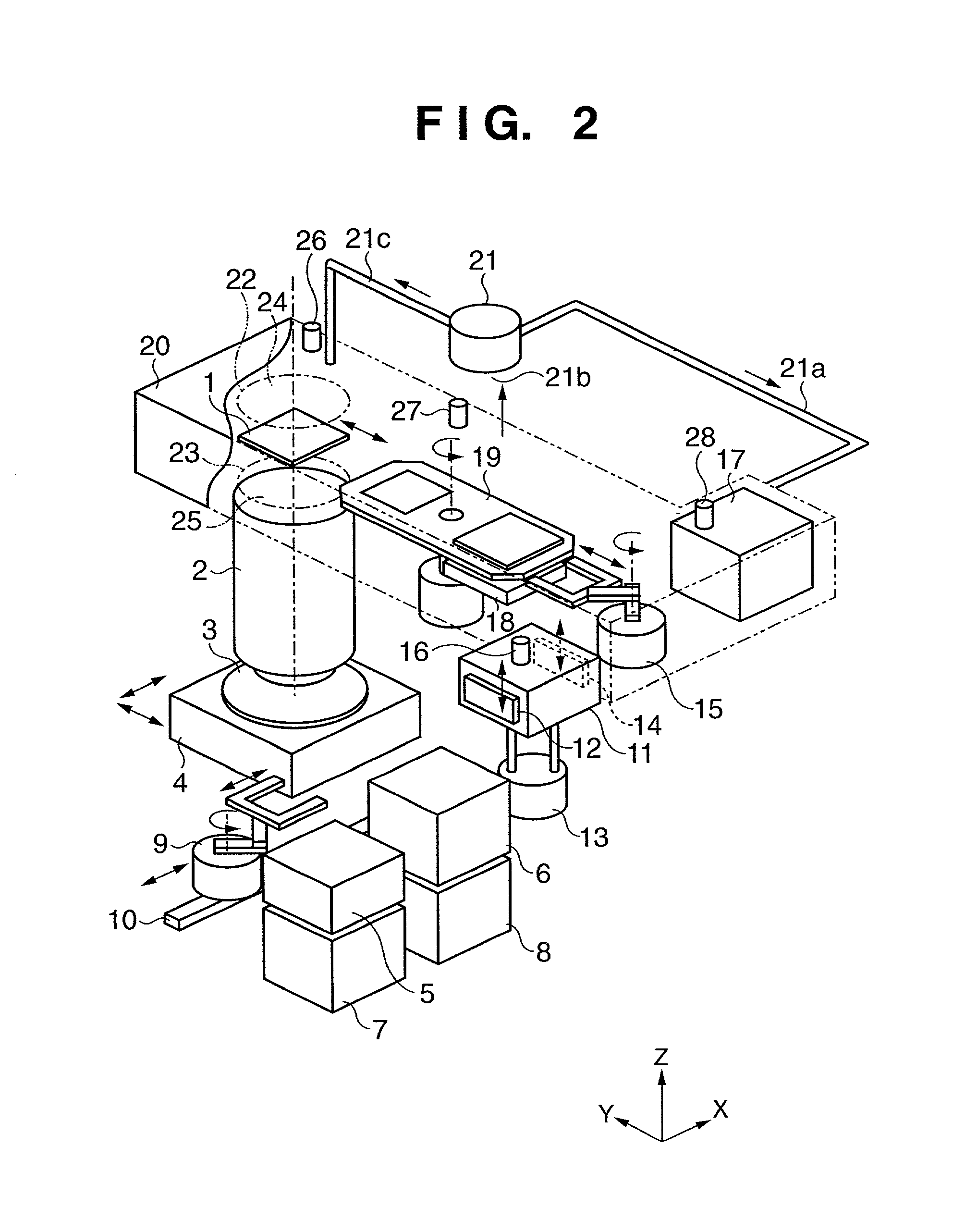
[0052] the present invention will be described with reference to FIG. 2.

[0053] FIG. 2 shows a modification of the nitrogen gas supply form to the closed vessel 20 in FIG. 1. The same reference numerals as in FIG. 1 denote the same parts, and a description thereof will be omitted.

[0054] Nitrogen gas from a nitrogen gas purge control unit 21 is supplied into a closed vessel 20 via pipe systems 21a and 21c. Similar to the first embodiment, the pipe system 21a supplies nitrogen gas to the vicinity of a temporary reticle stock unit 17. The pipe system 21c supplies nitrogen gas to the vicinity of a reticle stage (not shown), i.e., exposure position. A pipe system 21b discharges gas in the closed vessel 20. Similar to the first embodiment, gas may be directly discharged from the exposure apparatus, or the nitrogen gas purge control unit 21 may incorporate a circulation path extending to the pipe systems 21a and 21c via a cleaning means (not shown) such as a filter for removing the impurity...


PUM


Abstract

An exposure apparatus for transferring a pattern on a master to a substrate via an optical system includes a first housing for surrounding the exposure position of the master, a second housing for stocking the master, and a third housing for transferring the master between the inside and outside of the first housing. The interior of each housing is controlled to a predetermined atmosphere.

Description

FIELD OF THE INVENTION[0001] The present invention relates to an exposure apparatus for exposing a substrate such as a wafer or glass plate coated with a photosensitive agent to a circuit pattern on a master such as a reticle or mask in the lithography step for manufacturing various devices such as a semiconductor element, liquid crystal element, and thin-film magnetic head and, particularly, to a master transfer system for the exposure apparatus.BACKGROUND OF THE INVENTION[0002] An exposure apparatus for manufacturing a semiconductor integrated circuit irradiates a wafer with an exposure beam of various wavelength bands in accordance with a circuit pattern. An exposure beam emitted by a light source illuminates a reticle via an illumination optical system. A fine circuit pattern formed on the reticle is imaged onto a wafer via a projection optical system by exposure and transfer.[0003] In order to increase the integration degree of a semiconductor integrated circuit, the circuit pa...

Claims


Application Information

Patent Timeline
IPC IPC(8): G03B27/42G03F7/20G03F7/22H01L21/027H01L21/677
CPCG03B27/42G03F7/70841G03F7/70741
Inventor MIWA, YOSHINORI
Owner CANON KK
Learn More