
Cationically polymerizable resist underlayer film-forming composition

a technology of polymerizable resist and composition, which is applied in the field of lithographic cationically polymerizable resist underlayer film-forming composition, can solve the problems of resolution failure, resist pattern having a desired shape cannot be formed, and resist pattern dimension variation, so as to achieve high filling properties of the inside of the hole, reduce the viscosity, and improve the effect of etching ra

Active Publication Date: 2019-10-08
NISSAN CHEM CORP
View PDF13 Cites 0 Cited by
  • Summary
  • Abstract
  • Description
  • Claims
  • Application Information

AI Technical Summary

Benefits of technology

[0029]According to the resist underlayer film-forming composition for lithography of the present invention, an excellent underlayer film that has a dry etching rate higher than that of a photoresist and does not cause intermixing with the photoresist can be provided.
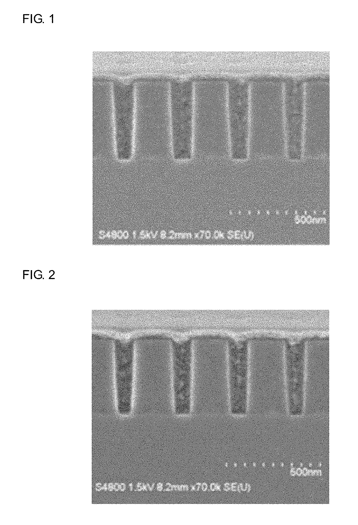
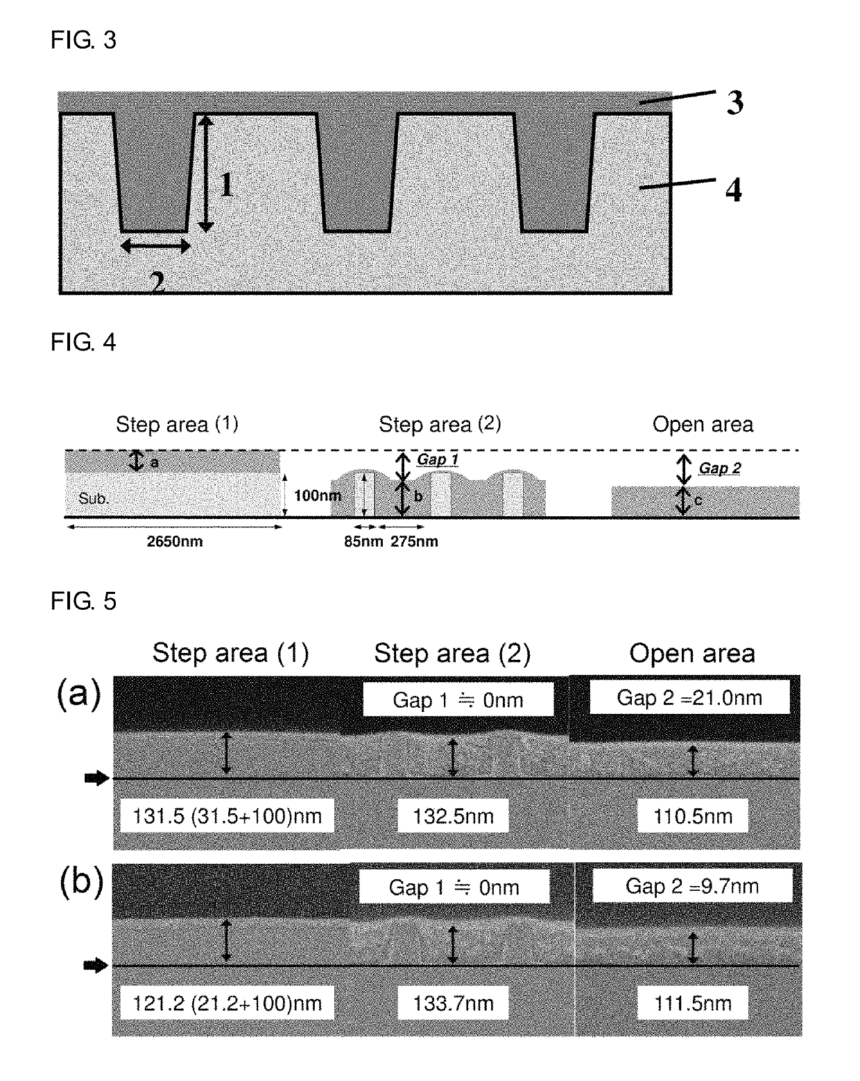
[0030]According to the resist underlayer film-forming composition for lithography of the present invention, a surface of a semiconductor substrate having a hole of which the aspect ratio of a height to a diameter is one or more can be flattened.
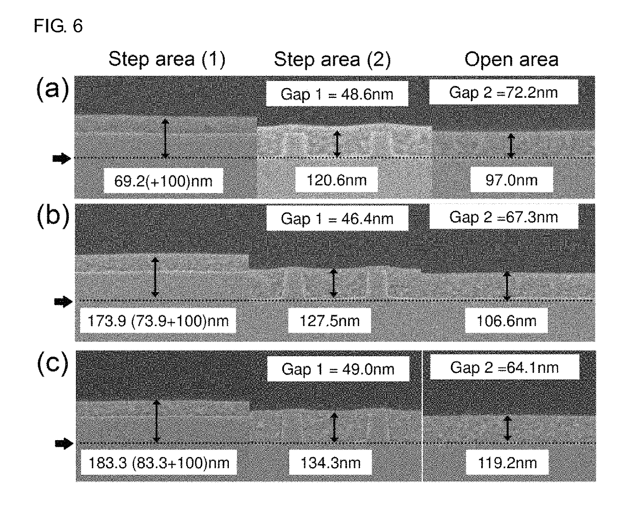
[0031]The resist underlayer film-forming composition for lithography of the present invention has a viscosity lower than that of a conventional resin type film-forming composition in which an acrylic resin or the like is used. Therefore, high filling properties of inside of the hole can be achieved without generation of voids (gaps). Further, the resist underlayer film-forming composition can flatten a recess and a projection of a substrate having a hole by embedding. In addition, the underlayer film can be formed without addition of a crosslinker. For this reason, influence of film shrinkage due to use of the crosslinker can be suppressed. Moreover, the uniformity of film thickness of a photoresist to be formed by coating on the underlayer film, or the like, can be enhanced. Therefore, even by a process using the substrate having a hole, a favorable pattern profile of the photoresist can be formed.
[0032]According to the resist underlayer film-forming composition for lithography of the present invention, an underlayer film that can be used as an anti-reflective coating or a flattening film can be formed. Accordingly, a photoresist pattern can be easily formed with high precision by a lithography process in the production of a semiconductor device.

Problems solved by technology

Therefore, a resist pattern having a desired shape cannot be formed.
That is, it is known that the presence of the standing wave can cause variation in dimension of the resist pattern and resolution failure.

Method used


Image

  • Cationically polymerizable resist underlayer film-forming composition
  • Cationically polymerizable resist underlayer film-forming composition
  • Cationically polymerizable resist underlayer film-forming composition

Examples


synthesis example 1

[0116]A solution obtained by mixing 100.18 g (30% by mass PGMEA solution) of tetra(3,4-epoxycyclohexylmethyl)butanetetracarboxylate modified ε-caprolactone (product name EPOLEAD GT401 available from Daicel Corporation), 3.1287 g of 9-anthracenecarboxylic acid, 0.0807 g of benzyl tetraethylammonium chloride, and 7.6687 g of propylene glycol monomethyl ether acetate (PGMEA) was warmed to 140° C., and reacted under a nitrogen atmosphere for 24 hours, to obtain a solution containing a compound of the following Formula (A-1) (solid content: 23.3% by mass). The obtained solution containing the compound was analyzed by GPC. The weight average molecular weight in terms of standard polystyrene was about 1,100.

[0117]

synthesis example 2

[0118]A solution obtained by mixing 50.00 g (30% by mass PGMEA solution) of tetra(3,4-epoxycyclohexylmethyl)butanetetracarboxylate modified ε-caprolactone (product name EPOLEAD GT401 available from Daicel Corporation), 3.6028 g of 9-anthracenecarboxylic acid, 0.0915 g of benzyl tetraethylammonium chloride, and 8.6164 g of PGMEA was warmed to 140° C., and reacted under a nitrogen atmosphere for 24 hours, to obtain a solution containing compounds of the following Formulae (A-1) to (A-3) (solid content: 26.2% by mass). The obtained solution containing the compounds was analyzed by GPC. The weight average molecular weight in terms of standard polystyrene was about 1,200.

[0119]

synthesis example 3

[0120]3.00 g of glycidyl methacrylate, 26.213 g of 2-hydroxypropyl methacrylate, and 1.753 g of dimethyl 2,2-azobisisobutylate were dissolved in 30.966 g of propylene glycol monomethyl ether, and the mixture was heated. The mixture was added to 77.416 g of propylene glycol monomethyl ether of which the temperature was kept to 90° C. by heating, to cause a reaction for 24 hours. As a result, a solution of copolymer of glycidyl methacrylate with 2-hydroxypropyl methacrylate was obtained.

[0121]To 120.00 g of the solution containing 24.00 g of this copolymer, 1.70 g of 9-anthracenecarboxylic acid, 0.046 g of benzyltriethylammonium chloride, and 0.4971 g of propylene glycol monomethyl ether were added, and the mixture was heated to cause a reaction at 120° C. for 24 hours. As a result, a solution containing a copolymer having a structural unit of the following Formula (9) was obtained. The obtained copolymer was analyzed by GPC. The weight average molecular weight in terms of standard po...


PUM

PropertyMeasurementUnit
pore diameteraaaaaaaaaa
temperatureaaaaaaaaaa

Abstract

There is provided a composition for forming a resist underlayer film for lithography that can be used as an underlayer anti-reflective coating that decreases the reflection of irradiated light during exposure from a semiconductor substrate toward the photoresist layer that is formed on the semiconductor substrate and in particular, can be suitably used as a flattening film for flattening a semiconductor substrate having a recess and a project by embedding, in a lithography process for production of a semiconductor device. A resist underlayer film-forming composition for lithography comprising (A) an alicyclic epoxy compound having an alicyclic skeleton and one or more epoxy groups, and a light absorption moiety, in the molecule, (B) a thermal acid generator, and (C) a solvent.

Description

TECHNICAL FIELD[0001]The present invention relates to a cationically polymerizable resist underlayer film-forming composition for lithography that functions as an anti-reflective coating during exposure and can flatten a semiconductor substrate having a recess by embedding using a liquid epoxy compound.BACKGROUND ART[0002]For example, the formation of a finer resist pattern on a substrate by a photolithography technique including an exposure step using a KrF excimer laser or an ArF excimer laser as a light source as compared with a conventional technique has been known in the production of a semiconductor element. Light of the KrF excimer laser or ArF excimer laser (incident light) incident to a resist film before the formation of the resist pattern is reflected on a surface of the substrate to generate a standing wave in the resist film. Due to the influence of the standing wave, the shape of pattern edge collapses. Therefore, a resist pattern having a desired shape cannot be forme...

Claims


Application Information

Patent Timeline
Patent Type & Authority Patents(United States)
IPC IPC(8): G03F7/11C09D163/00C08G59/20G03F7/09
CPCG03F7/11C08G59/20G03F7/091C09D163/00
Inventor OGATA, HIROTOKIMURA, SHIGEOUSUI, YUKIOHASHI, TOMOYAKISHIOKA, TAKAHIRO
Owner NISSAN CHEM CORP
Learn More