
Printing method and printing device

A printing method and printing device technology, applied to printing devices, printing, printing machines, etc., can solve problems such as poor mold release, and achieve the effect of improving transferability and preventing ink from piling up

Inactive Publication Date: 2007-05-09
SUMITOMO RUBBER IND LTD +1
View PDF1 Cites 5 Cited by
  • Summary
  • Abstract
  • Description
  • Claims
  • Application Information

AI Technical Summary

Problems solved by technology

In the case of printing at a size greater than G6, since it takes about 20 seconds from the ink coating on the surface of the silicon wafer to the end of the coating, for example, the relief plate should be placed on the ink coating surface When the ink is transferred and removed by pressing, the ink at the beginning of application has been fully dried, but the ink at the end of application has not yet been fully dried. Therefore, the release of the ink at the beginning of application on the convex part of the relief plate is good, On the other hand, the ink at the end of the application is cut off, and the mold release becomes poor.

Method used


Image

  • Printing method and printing device

Examples


Embodiment 1

[0097] [Silicone blanket]

[0098] Prepare a support film layer containing polyethylene terephthalate with a thickness of 350 μm and a silicone rubber (manufactured by Sumitomo Rubber Co., Ltd., room temperature curing type silicone rubber, JIS-A40) with a thickness of 600 μm. A silicone blanket (10-point average surface roughness: 0.1 μm) of a silicone rubber layer on the surface was wound on a metal cylinder. The outer diameter of the silicone blanket is 500 mm, and the length in the axial direction is 1000 mm.

[0099] [Bump version]

[0100] A concavo-convex plate in which protrusions are formed of metal formed in a stripe pattern with a line width of 100 μm, a pitch of 300 μm, and a depth of 20 μm was prepared. The surface of this concave-convex plate was subjected to scratch-resistant processing by hard chrome treatment (thickness: 10 μm), and further, mirror-finished by polishing treatment.

[0101] [Preparation of ink]

[0102] With polyester-melamine resin 10 weig...

Embodiment 2

[0115] The method was the same as in Example 1, except that nitrogen gas was continuously blown from the gas nozzle to the ink-coated surface before the solvent in the ink was sucked by the suction nozzle after the ink was applied to the surface of the silicone blanket. method, ink was printed on a glass substrate.

[0116] More specifically, the gas nozzle opens in a long and thin rectangular shape along the axis of the silicone blanket. The width of the horizontal opening is set to be the same as the full width of the silicone blanket, and the width of the vertical opening is set to 100 μm. . In addition, the distance between the surface of the silicone blanket and the gas nozzle along the radial direction of the silicone blanket was set to 100 μm. In addition, within 3 seconds after the ink was applied to the surface of the silicone blanket with a slit die coater, ink previously filtered through a 0.3 μm membrane filter was blown from a gas nozzle at 10 m / s. Nitrogen at 2...


PUM


Abstract

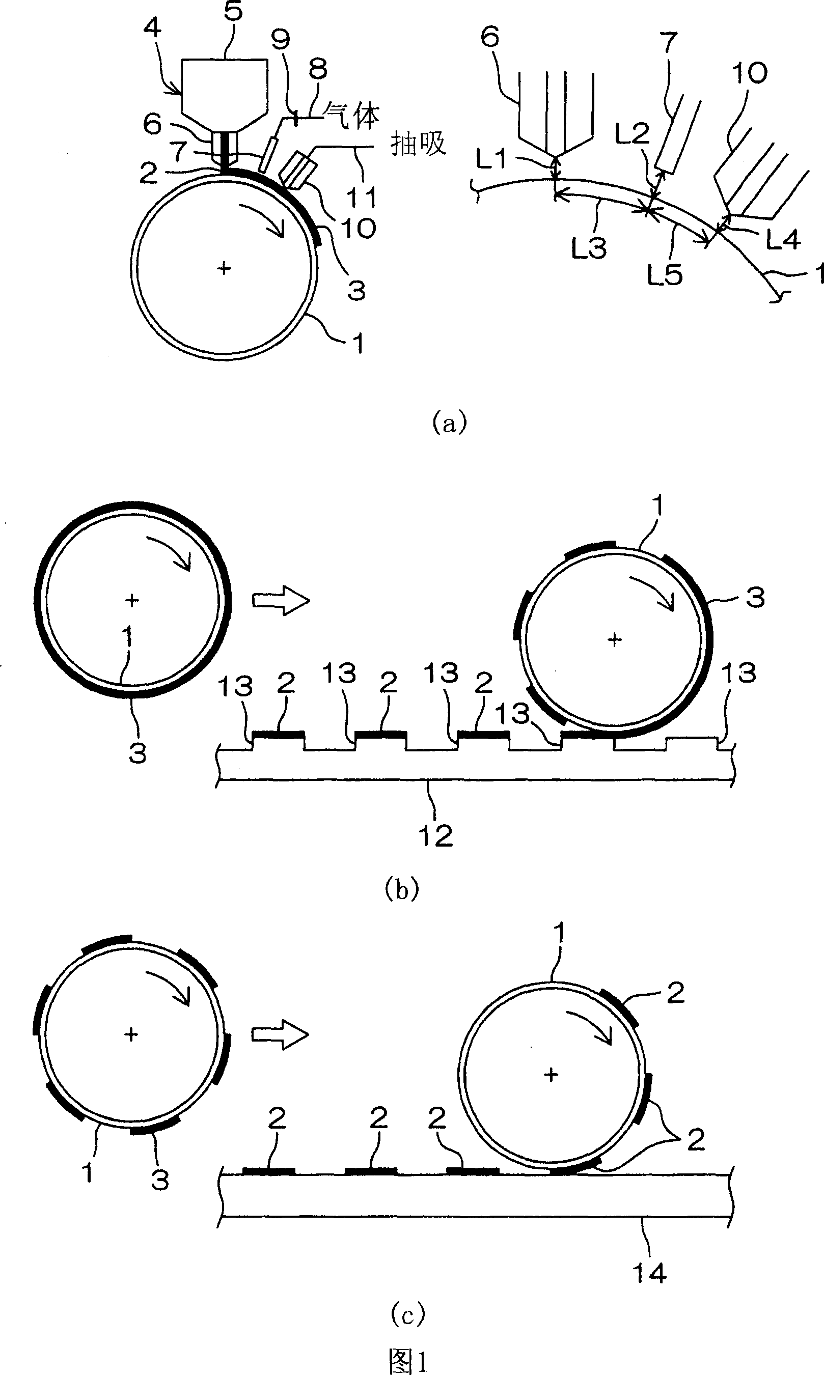
Provided is a printing method which can form a uniform ink coating surface with stable coating properties, on the surface of a silicone blanket, prevent an ink from piling by improving transferability, and further, meet the requirements of an oversized printable object, and a printing device to be used for this printing method. In this printing method, the ink is applied by a slit die coater so as to allow forming of a coating surface of the ink on the surface of a silicone blanket, then a drying gas is blown to the coating surface of the ink from a gas nozzle and a solvent contained in the ink is sucked by a suction nozzle. After that, the coating surface of the ink is removed partially by rolling the silicone blanket over an indented plate, and the coating surface of the residual ink is transferred to the surface of a substrate.

Description

technical field [0001] The present invention relates to a printing method and a printing device, and more specifically, to an offset printing method based on reverse printing and a printing device used in the method. Background technique [0002] As an offset printing method based on reverse printing, there has been proposed an image forming method consisting of the following steps: a coating step of applying ink to the entire surface of a silicon wafer to form a coated surface; Relief plate formed in a predetermined shape, and transfer to the convex part of the relief plate to remove the ink removal process; Transfer process of transferring ink remaining on the coated surface to the base plate. By this method, proposals have been made to eliminate moire, eliminate pockmarks, improve resolution, flatness, and eliminate ghosting (for example, refer to JP-A-11-58921.). [0003] However, in the above-mentioned method, at first, ink needs to be coated on the entire surface of t...

Claims


Application Information

Patent Timeline
Patent Type & Authority Applications(China)
IPC IPC(8): B41M1/00B41F17/00
CPCB41M1/02B41M1/10B41M5/03B41N10/02
Inventor 近藤康彦浜冈兴一郎星名升一
Owner SUMITOMO RUBBER IND LTD
Learn More