Substrate treatment apparatus, substrate treatment method and substrate manufacturing method

a substrate treatment and substrate technology, applied in the field of substrates, can solve the problems of line-shape stains, not being considered anymore, watermarks, etc., and achieve the effects of reducing foreign matter, high washing effect, and reducing drying stains and foreign matter

Inactive Publication Date: 2005-02-03
HITACHI HIGH-TECH ELECTRONICS ENGINEERING CO LTD
View PDF5 Cites 19 Cited by
  • Summary
  • Abstract
  • Description
  • Claims
  • Application Information

AI Technical Summary

Benefits of technology

[0009] The purpose of the present invention is to reduce an amount of the treatment liquid used when drying the substrate using the air knife.
[0010] Another purpose of the present invention is to prevent the watermarks being generated and dry the substrate evenly without the drying stains when drying the substrate using the air knife.
[0011] Another purpose of the present invention is to dry the surface of the substrate, which has the water repellency strongly on its surface, evenly without the drying stains while obtaining the high washing effect and the high foreign matter removal effect by the sloping carry system.

Problems solved by technology

However, since the area of the substrate becomes larger due to the enlargement of the flat panel display in recent years, a large amount of the treatment liquid is needed in order to form the treatment liquid layer evenly on the surface of the substrate.
It is difficult to form a washing water layer evenly on the surface of the substrate, which has the water repellency strongly, so that areas without the washing water layer appear on the surface of the substrate.
Then, drops of the washing water, which are blown away with the air from the air knife, adhere to the areas without the washing water layer and result in drying stains called watermark.
Although such watermarks had been conventionally permitted to some extent, they can not be disregarded anymore since they cause a problem of appearance and surface resistance variations when the pitch of the circuit patterns, which are formed on the surface of the substrate, becomes finer and finer.
For this reason, there was a problem that traces of the small drops, which were moved on the surface of the substrate, result in line-shape stains.
Moreover, there was a problem that the foreign matters remain along the traces of the small drops, which were moved on the surface of the substrate.

Method used


Image

  • Substrate treatment apparatus, substrate treatment method and substrate manufacturing method
  • Substrate treatment apparatus, substrate treatment method and substrate manufacturing method
  • Substrate treatment apparatus, substrate treatment method and substrate manufacturing method

Examples


Embodiment Construction

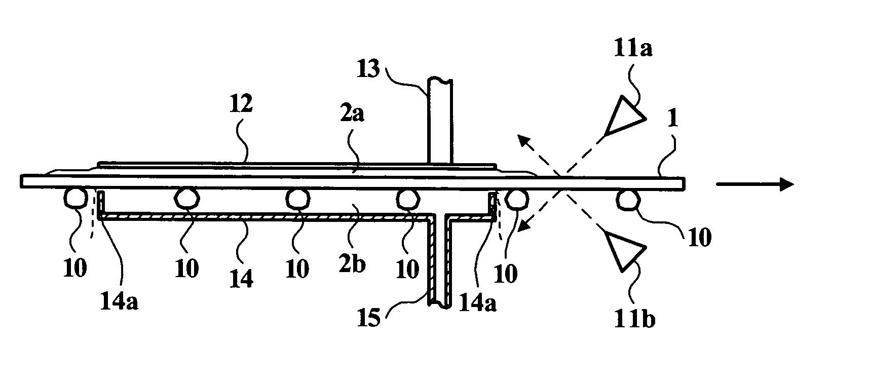
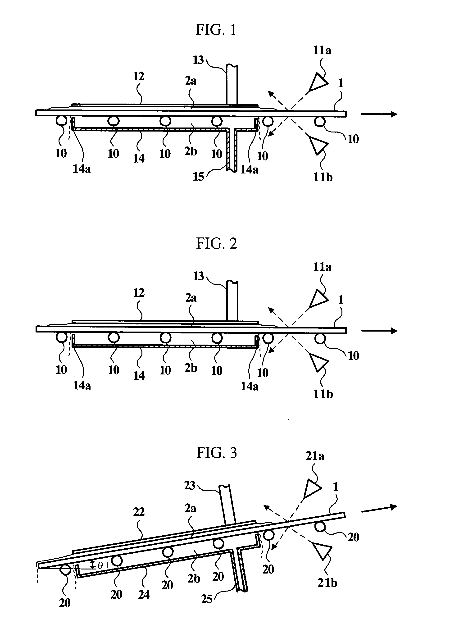
[0033] Further details are explained below with the help of examples illustrated in the attached drawings. FIG. 1 is a side view including some sections showing an example of the substrate treatment apparatus according to the present invention. This example moves a substrate horizontally. The substrate treatment apparatus comprises a plurality of rollers 10, air knives 11a and 11b, an upper board 12, a pipe 13, a lower board 14 and a pipe 15.

[0034] A substrate 1 is mounted on the rollers 10 and moved in a substrate moving direction shown by an arrow with the rotation of the rollers 10. Each roller 10 is arranged a certain distance apart each other in the substrate moving direction and rotated at a predetermined speed by the drive equipment, which is not illustrated. Each roller 10 is installed at the same height horizontally so that the rollers 10 move the substrate 1 horizontally.

[0035] Above the substrate 1 mounted on the rollers 10, the upper board 12 is prepared through a widt...


PUM

PropertyMeasurementUnit
Temperatureaaaaaaaaaa
Angleaaaaaaaaaa
Flow rateaaaaaaaaaa

Abstract

Above a substrate mounted on rollers, an upper board is prepared a predetermined distance apart from the substrate. A pipe fills a space between the upper board and the substrate with washing water by supplying the washing water at a predetermined flow rate. A washing water layer is formed evenly on an upper surface of the substrate when the substrate passes below the upper board. Below the substrate, a lower board is prepared a predetermined distance apart from the substrate. A pipe fills a space between the lower board and the substrate with the washing water by supplying the washing water at a predetermined flow rate. A washing water layer is formed evenly on a lower surface of the substrate when the substrate passes above the lower board. The air emitted from an air knife is sprayed to the upper / lower surface of the substrate slantingly at a predetermined incident angle in an opposite direction of a substrate moving direction. The washing water is pushed away and removed from the upper / lower surface of the substrate.

Description

FIELD OF THE INVENTION [0001] The present invention relates to a substrate treatment apparatus and a substrate treatment method for drying a substrate by spraying the air to the substrate using an air knife, and a substrate manufacturing method employing them. It especially relates to the substrate treatment apparatus and the substrate treatment method suitable for drying the large-size substrate or the substrate having the water repellency strongly on its surface, and the substrate manufacturing method employing them. BACKGROUND OF THE INVENTION [0002] In a manufacturing process of a panel substrate for a flat panel display, such as a liquid crystal display, a plasma display and the like, a chemical liquid treatment, such as development, etching, etc., is performed in order to form circuit patterns, a color filter, etc. on the substrate. Also in a manufacturing process of a semiconductor device, the chemical liquid treatment, such as development, etching, etc., is performed in orde...

Claims


Application Information

Patent Timeline
IPC IPC(8): F26B5/14F26B15/12F26B21/00H01L21/00
CPCF26B5/14H01L21/67034F26B21/004F26B15/12
Inventor MORIGUCHI, YOSHIHIROIZAKI, RYOYASUIKE, YOSHITOMOKAMAISHI, TAKAOISHIDA, TAKAHISA
Owner HITACHI HIGH-TECH ELECTRONICS ENGINEERING CO LTD
Why Eureka
Try Eureka