Carbon nanotube structure-selective separation and surface fixation

A technology of carbon nanotubes and nanotubes, which is applied in the field of highly selective separation, concentration and refining of carbon nanotubes, and can solve the problem of poor separation accuracy

Inactive Publication Date: 2007-02-28
JAPAN SCI & TECH CORP
View PDF5 Cites 16 Cited by
  • Summary
  • Abstract
  • Description
  • Claims
  • Application Information

AI Technical Summary

Problems solved by technology

However, it is completely different from the principle of the present invention, and it is not as good as the technology of the present invention in terms of separation accuracy

Method used


Image

  • Carbon nanotube structure-selective separation and surface fixation
  • Carbon nanotube structure-selective separation and surface fixation
  • Carbon nanotube structure-selective separation and surface fixation

Examples


Embodiment 1

[0201] 1.1 Depositing metal on carbon nanotubes

[0202] Carbon nanotubes (CarboLex AP-Grade SWNT (SWNT: purity 50-70%)) in 1% sodium dodecyl sulfate (SDS) aqueous solution were subjected to ultrasonic dispersion treatment for 15 minutes under the conditions of 24°C and 12000 rpm, and injected A filter (0.2 μm pore size filter) filters the supernatant and performs additional sonication and centrifugal separation under the same conditions to obtain a micellar dispersion.

[0203] Next, methanol (methanol: 99.8% purity, Infinity PureGrade; available from Wako Pure Chemical Industries, Ltd.) as an electron donor was added to the dispersion to a concentration of 0.1%. Add the following three different metal ion solutions to the solution obtained above to prepare three solutions with different metal ions.

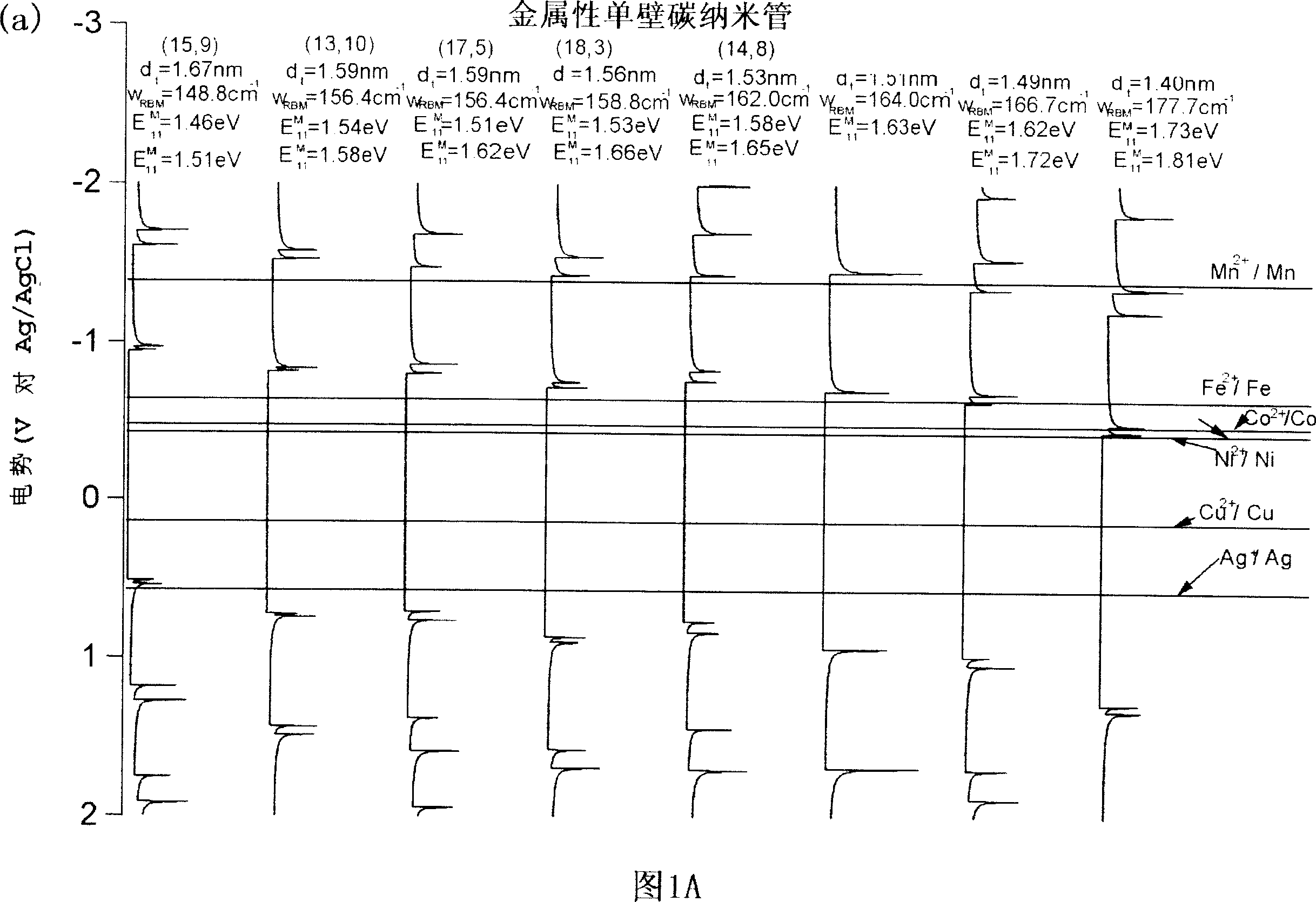
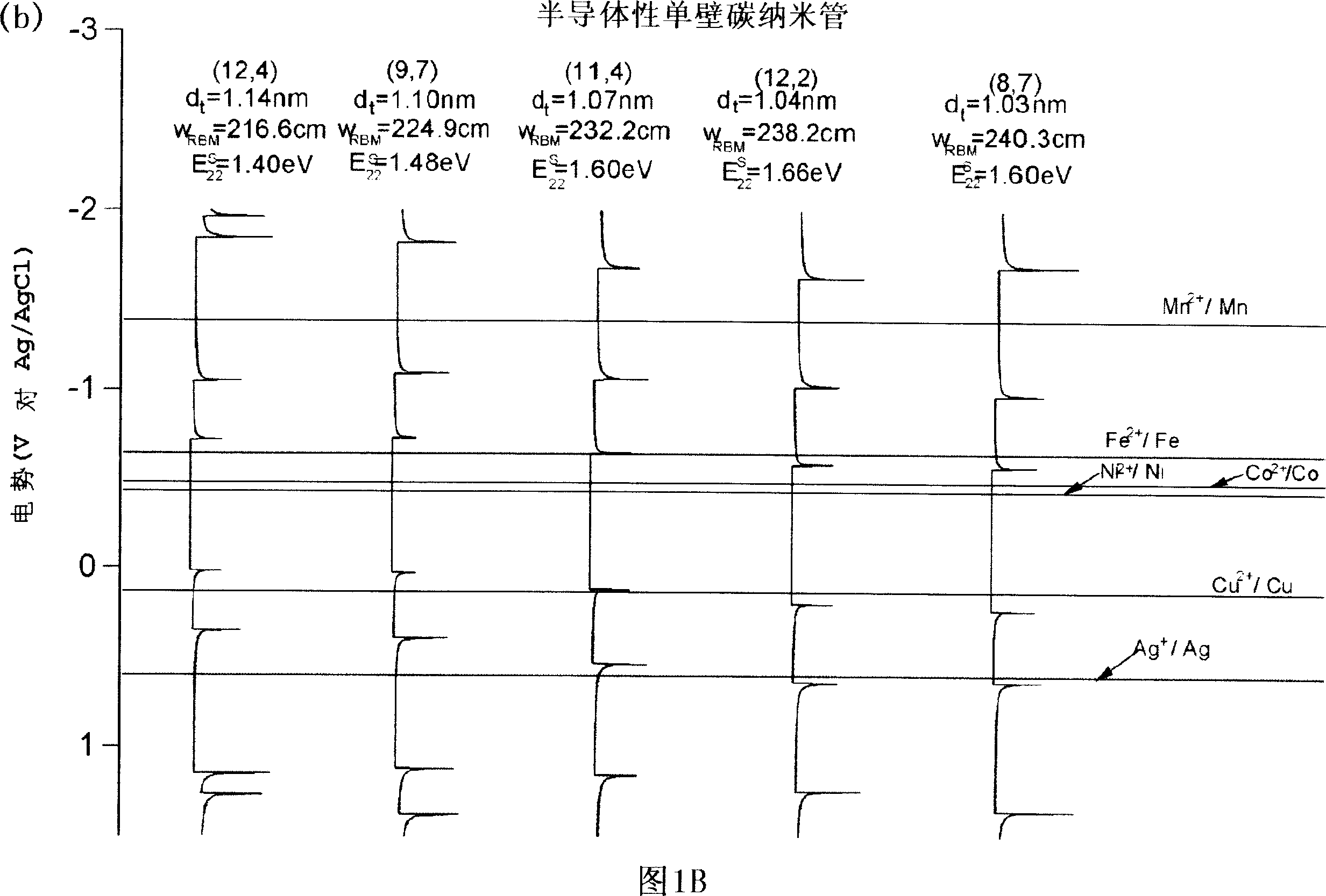
[0204] I)0.1M Fe(NH 4 ) 2 (SO 4 ) 2 Aqueous solution

[0205] II) 0.1M CoCl 2 Aqueous solution

[0206] III) 0.1M MnCl 2 Aqueous solution

[0207] The three solutions prepared in th...

Embodiment 2

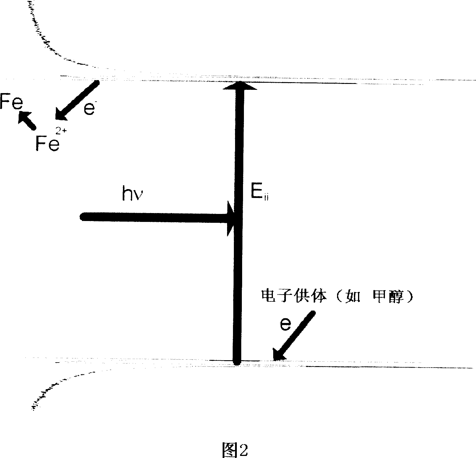
[0213] Fig. 8 is a diagram showing the structure of an apparatus according to an embodiment of the present invention. Different wavelengths of 1064nm (λ1), 785nm (λ2) and 514nm (λ3) are used as the illumination light source for photoelectrochemical metal deposition. The micelle dispersion liquid is obtained by dispersing and purifying the carbon nanotubes in a 1% sodium lauryl sulfate aqueous solution, which is used as a solution containing carbon nanotubes. Fix the thin film glass in the reaction vessel, and add Fe(NH 4 ) 2 (SO 4 ) 2 To the concentration of 0.1M, the substrate was irradiated with light of wavelength (λ1, λ2, or λ3) for 10 minutes. After the deposited metal carbon nanotubes are accumulated on the substrate, the carbon nanotubes are cleaned with sulfuric acid, and Raman spectroscopy is performed in the radial breathing mode to determine the chirality vector of the deposited carbon nanotubes. In the part where the λ1 wavelength is used for illumination, it is found ...

Embodiment 3

[0216] Fig. 9 shows a graph of an experiment conducted similarly to the above-mentioned Example 2 with an additional step of flowing a solution containing carbon nanotubes and continuously supplying a dispersion liquid of the contained carbon nanotubes. As a result, carbon nanotubes can be selectively deposited similarly to the above, resulting in an increase in deposition amount of two to ten times.


PUM

PropertyMeasurementUnit
diameteraaaaaaaaaa

Abstract

A method of separating, concentrating or purifying uniform carbon nanotubes with desired properties (diameter, chiral vector, etc) in a highly sensitive manner by the use of structure-sensitive properties peculiar to carbon nanotubes; and an apparatus therefor. There is provided a method of separating, concentrating, or purifying carbon nanotubes with the desired properties contained in a sample, comprising the steps pf (a) irradiating a sample containing carbon nanotubes with light; and (b) selecting carbon nanotubes with desired properties. In a preferred embodiment, the light irradiation of the step (a) can be carried out in the presence of a metal so as to cause specified carbon nanotubes to selectively induce a photocatalytic reaction, resulting in metal deposition. Further, in a preferred embodiment, a given magnetic filed can be applied in the steps (b) so as to attain accumulation or concentration or carbon nanotubes with metal deposited.

Description

Technical field [0001] The invention relates to a method and equipment for highly selective separation, concentration and purification of carbon nanotubes (CNT). The invention also relates to the high-purity carbon nanotubes separated by the method of the invention, and their films and arrays. The present invention further provides optical devices or electronic devices using the carbon nanotube film. Background technique [0002] Carbon nanotubes are new substances discovered by Sumio Iijima in 1991. They can exhibit metallic and / or semiconductor properties according to their diameter and the way the tube is wound. The physical properties of carbon nanotubes are completely different depending on the structure of the tube. Currently, research in this field is actively carried out. In addition, carbon nanotubes are a kind of next-generation materials, many of which are expected to be used in devices, etc., and have application prospects in the fields of electronics and energy. [0...

Claims


Application Information

Patent Timeline
Patent Type & Authority Applications(China)
IPC IPC(8): C01B31/02B82B3/00G01N27/00G01N30/88G01N37/00G01P15/00H01M4/88H01M4/96G01N13/14B01D39/20B82B1/00B82Y15/00B82Y30/00B82Y35/00B82Y40/00B82Y99/00G01P15/08H01M4/86
CPCH01M4/8605Y10S977/848Y02E60/50B82Y40/00B82Y15/00B82Y30/00G01P15/08Y10S977/745Y10S977/751C01B2202/36Y10S977/845C01B2202/02G01N2030/8859H01M4/9083C01B2202/30H01M4/96C01B31/0266G01P15/0802Y10S977/748C01B32/172C01B32/17
Inventor 村越敬
Owner JAPAN SCI & TECH CORP
Why Eureka
Try Eureka