
High-toughness mining chain steel and manufacturing method thereof

A manufacturing method, chain steel technology, applied in the direction of manufacturing tools, metal chains, furnaces, etc., can solve problems such as brittle fracture, safety accidents, economic losses, etc.

Active Publication Date: 2021-08-31
BAOSHAN IRON & STEEL CO LTD
View PDF9 Cites 7 Cited by
  • Summary
  • Abstract
  • Description
  • Claims
  • Application Information

AI Technical Summary

Problems solved by technology

[0006] For the humid mine environment conditions, the Mn-Cr-Ni-Mo alloy steel chain is subject to heavy load and dynamic impact, prone to stress corrosion, serious brittle fracture may occur, resulting in huge economic losses and even safety accidents

Method used

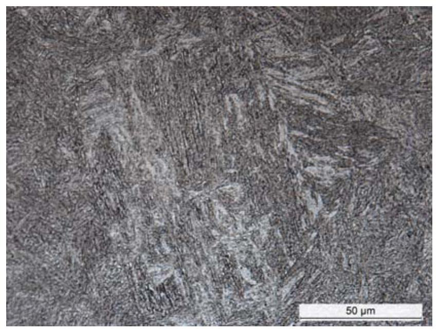
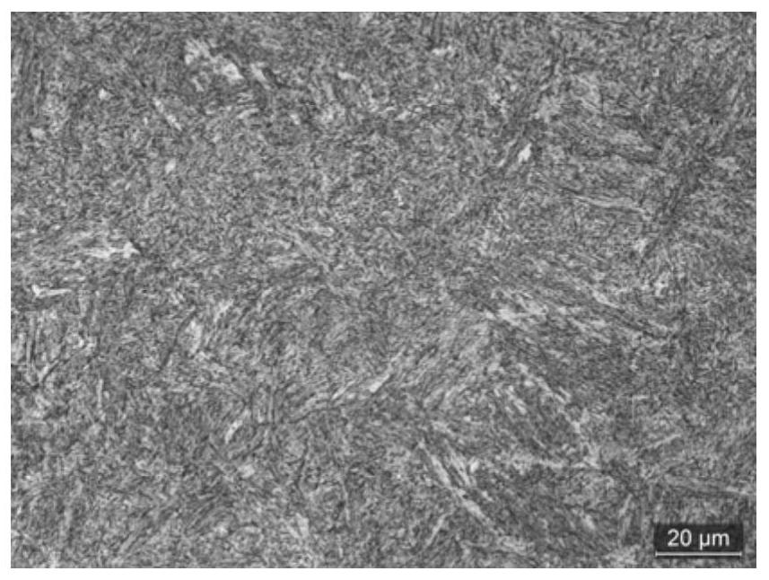

Image

  • High-toughness mining chain steel and manufacturing method thereof
  • High-toughness mining chain steel and manufacturing method thereof
  • High-toughness mining chain steel and manufacturing method thereof

Examples


Embodiment 1

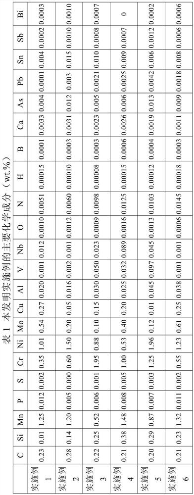
[0074] According to the chemical composition shown in Table 1, the electric furnace is smelted, and after refining and vacuum treatment, it is cast into a continuous casting slab, and the continuous casting slab is heated to 1050 ° C, and the holding time is 4 hours; The rolling temperature is 800°C, and the size of the middle billet is 200×200mm. The intermediate billet is heated to 1050°C, and the holding time is 24 hours. After being descaled by high-pressure water, rolling begins. The final rolling temperature is 850°C, and the finished bar size is φ50mm. Cool in air after rolling. The quenching heating temperature is 850°C, the heating time is 60min, the tempering temperature is 390°C, the tempering time is 90min, and air cooling after tempering.

Embodiment 2

[0076] The implementation is the same as in Example 1, wherein the heating temperature is 1080°C, the holding time is 3h, the final rolling temperature is 880°C, and the size of the intermediate billet is 220×220mm. The intermediate billet is heated to 1120°C, the holding time is ≥3h, the final rolling temperature is 850°C, and the specification of the finished bar is φ75mm. Cool in air after rolling. The quenching heating temperature is 870°C, the heating time is 100min, the tempering temperature is 550°C, the tempering time is 60min, and water cooling after tempering.

Embodiment 3

[0078] The implementation method is the same as that in Example 1, wherein the heating temperature is 1120° C., the holding time is 8 hours, the final rolling temperature is 940° C., and the size of the intermediate billet is 260×260 mm. The intermediate billet is heated to 1200°C, the holding time is 5h, the final rolling temperature is 880°C, and the specification of the finished bar is φ100mm. Cool in air after rolling. The quenching heating temperature is 890°C, the heating time is 150min, the tempering temperature is 430°C, the tempering time is 100min, and air cooling after tempering.


PUM

PropertyMeasurementUnit
Yield strengthaaaaaaaaaa
Tensile strengthaaaaaaaaaa
Impact energyaaaaaaaaaa

Abstract

The invention discloses high-toughness mining chain steel and a manufacturing method thereof. The high-toughness mining chain steel comprises the following components in percentage by weight: 0.20-0.28% of C, 0.01-0.40% of Si, 0.50-1.50% of Mn, less than or equal to 0.015% of P, less than or equal to 0.005% of S, 0.30-2.00% of Cr, 0.50-2.00% of Ni, 0.10-0.80% of Mo, 0.01-0.30% of Cu, 0.01-0.05% of Al, 0.001-0.10% of Nb, 0.001-0.10% of V, less than or equal to 0.00018% of H, less than or equal to 0.0150% of N, less than or equal to 0.0020% of O and the balance of Fe and inevitable impurities. The manufacturing process comprises the working procedures of smelting, refining, vacuum treatment, casting, heating, forging or rolling, quenching and tempering heat treatment and the like. The chain steel has high strength and good impact toughness, ductility and percentage reduction of area, can resist stress corrosion cracking, has good weather resistance, wear resistance and fatigue resistance, and can be used for engineering machinery, ocean engineering and other occasions needing high-strength and high-toughness steel.

Description

technical field [0001] The invention relates to high-strength steel, in particular to a high-strength and tough mine chain steel and a manufacturing method thereof. Background technique [0002] High-strength and tough steel bars are usually used in high-safety machinery and structural components. For example, mine circular link chains are key vulnerable parts of coal mining machinery. They should have high strength, high toughness, wear resistance, corrosion resistance and high fatigue performance etc. [0003] There are many studies on high-strength and tough steel at home and abroad. Usually, the appropriate chemical composition is selected, and the controlled rolling and cooling or quenching + tempering process are used to produce high-strength and tough steel. The production of high-strength steel by controlled rolling and controlled cooling will affect the overall uniformity of the mechanical properties of the steel due to the difficulty in controlling the rolling and...

Claims


Application Information

Patent Timeline
IPC IPC(8): C22C38/02C22C38/04C22C38/06C22C38/42C22C38/44C22C38/46C22C38/48C22C33/04B21C37/00C21D9/00
CPCC22C38/02C22C38/04C22C38/44C22C38/42C22C38/48C22C38/46C22C38/06C22C33/04B21C37/00C21D9/0087C21D2211/008C21D2211/002C21D2211/001C21D1/25C21D1/60C21D8/065C21D7/13C21D9/0081C22C38/54C22C38/60C22C38/008C22C38/002C22C38/001C21D8/0226B22D11/113B21J9/02B21L11/00C21D1/18C21D6/004C21D6/005C21D6/008C21D8/0263
Inventor 高加强赵四新王维章军
Owner BAOSHAN IRON & STEEL CO LTD
Learn More