X-ray source of pyroelectric crystal
A pyroelectric and crystal technology, applied in the field of physical instruments, can solve problems such as hot cathode consumption, high power, and high cost
- Summary
- Abstract
- Description
- Claims
- Application Information
AI Technical Summary
Problems solved by technology
Method used
Image

Examples
Embodiment 1
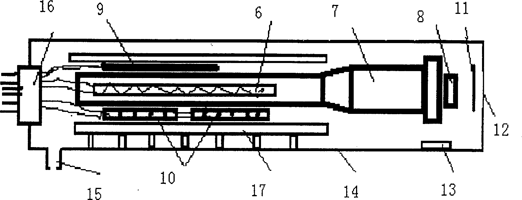
[0018] Embodiment 1: made as image 3 The X-ray emitter shown has a shell of φ30×80mm aluminum cylinder, and 0.2 grams of Y zeolite molecular sieve is placed in the shell as a getter, and the vacuum is pumped to 5×10 -3 torr to seal the case. The size is 8×5×2.5mm 3 LiTaO 3 The crystal is the emitter, 5mm away from the surface of the crystal, a 0.1mm thick iron-plated aluminum film is placed as a target, and the iron film faces the crystal. Two pieces of TES1-1703 semiconductor cooling plates are used in series to cool the crystal. Both the heater and the refrigerator are powered by a DC stabilized power supply with a voltage of 3-6V. The heating current is 0.5A, the duration is 3 minutes, the maximum temperature of the platinum resistance is 100-120°C, the cooling current is 2A, the duration is 5 minutes, the minimum temperature of the platinum resistance is 3-5°C. A high-purity germanium detector is used to detect the emitted X-rays, and the integral counting rate is ab...
Embodiment 2
[0019] Embodiment 2: The structure of X-ray emitter is schematically shown as image 3 , the shell is a φ30×80mm aluminum cylinder, and 0.2 grams of Y zeolite molecular sieve is placed in the shell as a getter, and the vacuum is pumped to 5×10 -3 torr to seal the case. The size is 8×3×2mm 3 cesium nitrate (CsNO 3 ) crystal as the emitter, 5mm away from the surface of the crystal, place 0.1mm thick gold foil as the target. The heater is not used during normal operation. The semiconductor refrigerator adopts three-stage refrigeration, the cooling current is 4A, and the duration is 5 minutes, and then the power is turned off to allow it to heat up naturally. During the heating process, a high-purity germanium detector is used to detect the emitted X-rays, and the characteristic spectral lines of gold Au L can be clearly seen in the accumulated energy spectrum obtained α (9.7keV) and Au L β (11.4keV).
Embodiment 3
[0020] Embodiment 3: The structure of the X-ray emitter is schematically shown as image 3 , the shell is a φ30×80mm aluminum cylinder, and 0.2 grams of Y zeolite molecular sieve is placed in the shell as a getter, and the vacuum is pumped to 1×10 -3 torr to seal the case. The size is 4×4×2.5mm 3 lithium niobate (LiNbO 3 ) crystal as the emitter, and a thin aluminum window with a thickness of 0.08mm at a distance of 10mm from the surface of the crystal doubles as a target. The semiconductor refrigerator is not used during normal operation, the heater operating voltage is 3-4V, the current is 0.3-0.4A, the heating duration is 5 minutes, and then stop the power supply and let it cool down naturally. During the cooling process, a beryllium window thin crystal NaI(Tl) detector is used to detect the emitted X-rays, and the integrated count rate can be obtained at 800-1100 / s.
PUM
 Abstract
Description
Claims
Application Information
 - Generate Ideas
- Intellectual Property
- Life Sciences
- Materials
- Tech Scout
- Unparalleled Data Quality
- Higher Quality Content
- 60% Fewer Hallucinations
Browse by: Latest US Patents, China's latest patents, Technical Efficacy Thesaurus, Application Domain, Technology Topic, Popular Technical Reports.
© 2025 PatSnap. All rights reserved.Legal|Privacy policy|Modern Slavery Act Transparency Statement|Sitemap|About US| Contact US: help@patsnap.com