


Quick Research
Generate reliable direction feasibility study reports for your R&D in just a few steps.

Technical Q&A
Discover and master advanced knowledge NOW. Basics, ideas, possibilities, all at once.

Find Solutions
As an expert in R&D theories, this can generate solutions to your technical problems instantly.

Evaluate Feasibility
Analyze your overall solution with one click, know your potential R&D risks in advance.

Monitor Landscape
Get weekly tech updates, stay abreast of the latest tech innovations and key insights.
Method of driving low energy ultrasonic metal welding by nanoparticles
A nanoparticle and metal welding technology, applied in welding equipment, metal processing equipment, non-electric welding equipment, etc., can solve the problems of unfavorable application of surface damage, reduce welding input energy, limit application prospects, etc., to achieve easy control of welding quality, Reduced risk, flexible and simple operation
- Summary
- Abstract
- Description
- Claims
- Application Information
AI Technical Summary
Problems solved by technology
Method used
Image

Examples
Embodiment 1
[0037] A kind of nanometer copper paste, it adopts following steps to prepare:
[0038] 1. Weigh 10 g of copper sulfate pentahydrate powder and add it to 40 ml of ethylene glycol, and heat to 75° C., and obtain solution A after the copper sulfate pentahydrate powder is completely dissolved.
[0039] II. Weigh 16 g of sodium hypophosphite powder and 10 g of polyvinylpyrrolidone into 160 ml of ethylene glycol, and heat to 75°C, and obtain solution B after the powder is completely dissolved.
[0040] III. Slowly add solution A to solution B, heat to 75°C, and react for 1.5 h to prepare dispersion C containing copper nanoparticles.
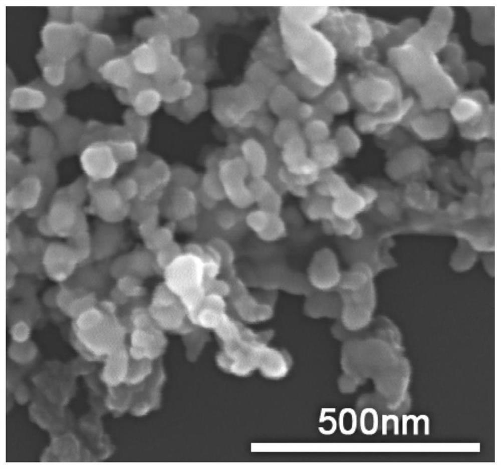
[0041] IV. After the dispersion liquid C is cooled to room temperature, it is centrifuged to separate the copper nanoparticles and the organic solvent. The separated copper nanoparticles were washed 2-4 times with a mixed solution D of deionized water and absolute ethanol in ultrasonic vibration. The size of the prepared nanoparticles is about 50nm,...
Embodiment 2
[0045] Ultrasonic welding of copper-copper metal with nano-copper paste interlayer and interface characterization
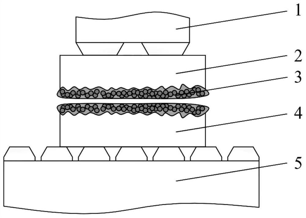
[0046] Such as figure 2Shown, adopt the nano copper paste ultrasonic welding copper-copper metal of embodiment 1, comprise the following steps:
[0047] 1, the material 2 to be welded on the upper layer and the material 4 to be welded on the lower floor are 20 mm × 10 mm × 0.5 mm copper strip, the connection surface of the material 2 to be welded and the material 4 to be welded is polished with 800# sandpaper to remove the surface oxide layer, and then Immerse in absolute ethanol and ultrasonically clean for 3 min.
[0048] II. Select the nano-particle paste of the middle layer as nano-copper paste, and screen-print the copper nano-particle paste with a thickness of 10 μm on the surface of the material 2 to be welded and the material 4 to be welded, and use figure 2 Place the upper and lower layers of copper strips to be soldered in the manner shown.
[0049...
Embodiment 3
[0056] Example 3 Ultrasonic welding of aluminum-copper metal with nano-copper paste interlayer
[0057] A method for ultrasonically welding aluminum-copper metals using copper nanoparticles, comprising the following steps:
[0058] I. The upper material to be welded is aluminum strip, and the lower layer to be welded is copper strip, with a size of 20 mm×10 mm×0.5 mm. The connecting surface of the material to be welded and the material to be welded is polished with 800# sandpaper to remove the surface oxide layer , and then ultrasonically cleaned by immersing in absolute ethanol for 3 min.
[0059] II. Select the nano-particle paste of the middle layer as nano-copper paste, and screen-print the nano-copper paste with a thickness of 10 μm on the material to be soldered and the surface of the material to be soldered, and use such as figure 2 Place the upper and lower layers of copper strips to be soldered in the manner shown.
[0060] III. According to the material properties...
PUM
| Property | Measurement | Unit |
|---|---|---|
| diameter | aaaaa | aaaaa |
| thickness | aaaaa | aaaaa |
| size | aaaaa | aaaaa |
Abstract
Description
Claims
Application Information
 - R&D Engineer
- R&D Manager
- IP Professional
- Industry Leading Data Capabilities
- Powerful AI technology
- Patent DNA Extraction
Browse by: Latest US Patents, China's latest patents, Technical Efficacy Thesaurus, Application Domain, Technology Topic, Popular Technical Reports.
© 2024 PatSnap. All rights reserved.Legal|Privacy policy|Modern Slavery Act Transparency Statement|Sitemap|About US| Contact US: help@patsnap.com